

Thin titanium sections can unlock major weight savings, internal volume, and corrosion resistance—but they also expose every weakness in a design. Unlike stiffer metals, Ti-6Al-4V and other titanium alloys can deflect under cutting loads, spring back after machining, and trigger chatter when walls, spans, and pockets are not balanced. A dimension that looks reasonable in CAD may become expensive scrap if the wall is too tall, too unsupported, or paired with sharp internal corners. This guide explains practical wall-thickness limits, the role of depth-to-thickness ratios, and the DFM choices—ribs, radii, fixturing assumptions, and tolerance planning—that help make thin-walled titanium parts manufacturable.
Why Thin-Walled Titanium Design Needs Special DFM
Designing components with thin-walled titanium structures presents a unique intersection of high-performance engineering and complex manufacturing challenges. Titanium alloys are highly sought after for their exceptional strength-to-weight ratio and superior corrosion resistance. However, these same material properties introduce severe complications during subtractive manufacturing.
The primary challenge stems from titanium’s relatively low elastic modulus. For instance, Ti-6Al-4V (Grade 5) has an elastic modulus of approximately 114 GPa, roughly half that of steel. When cutting forces are applied to thin titanium walls, the material tends to deflect or “spring back” rather than shear cleanly, which can drive scrap rates to 20–30% if unmitigated. This necessitates a rigorous Design for Manufacturability (DFM) approach to ensure dimensional stability, prevent chatter, and maintain tight geometric tolerances.
Key factors: wall thickness, span, ribs, and pockets
The success of a thin-walled titanium design relies heavily on managing the relationships between wall thickness, unsupported span length, and the integration of structural reinforcements like ribs and pockets. A critical metric in machining is the depth-to-thickness ratio. When a pocket depth exceeds 15 times the thickness of the adjacent wall (a 15:1 ratio), the risk of harmonic vibration—or chatter—increases exponentially. Chatter degrades surface finish and can lead to catastrophic tool failure or wall fracture.
To mitigate these risks, engineers must strategically segment long unsupported spans. Introducing orthogonal ribs or utilizing isogrid patterns breaks up continuous thin sections, increasing the localized moment of inertia. Pocket corner radii also play a vital role; tighter radii require smaller end mills, which must run at 40–60% lower feed rates and exert higher radial pressures, thereby exacerbating wall deflection.
Common use cases in aerospace, medical, and semiconductor parts
Thin-walled titanium is indispensable in industries where mass reduction and structural integrity are non-negotiable. In the aerospace sector, AS9100-compliant components such as UAV structural brackets, jet engine compressor blades, and satellite housings frequently push the limits of thin-wall machining, often requiring wall thicknesses down to 1.2 mm to meet stringent weight budgets.
The medical device industry leverages titanium’s biocompatibility for ISO 13485-certified implantable housings, pacemakers, and cranial plates. These applications routinely demand wall thicknesses between 0.3 mm and 0.5 mm to maximize internal volume for electronics while minimizing the patient’s physiological burden. Similarly, in the semiconductor equipment industry, titanium wafer-handling end effectors require highly rigid, ultra-thin profiles (often around 0.8 mm) to operate precisely within high-temperature, vacuum environments without introducing particulate contamination.
Realistic Wall Thickness Limits for Titanium Parts
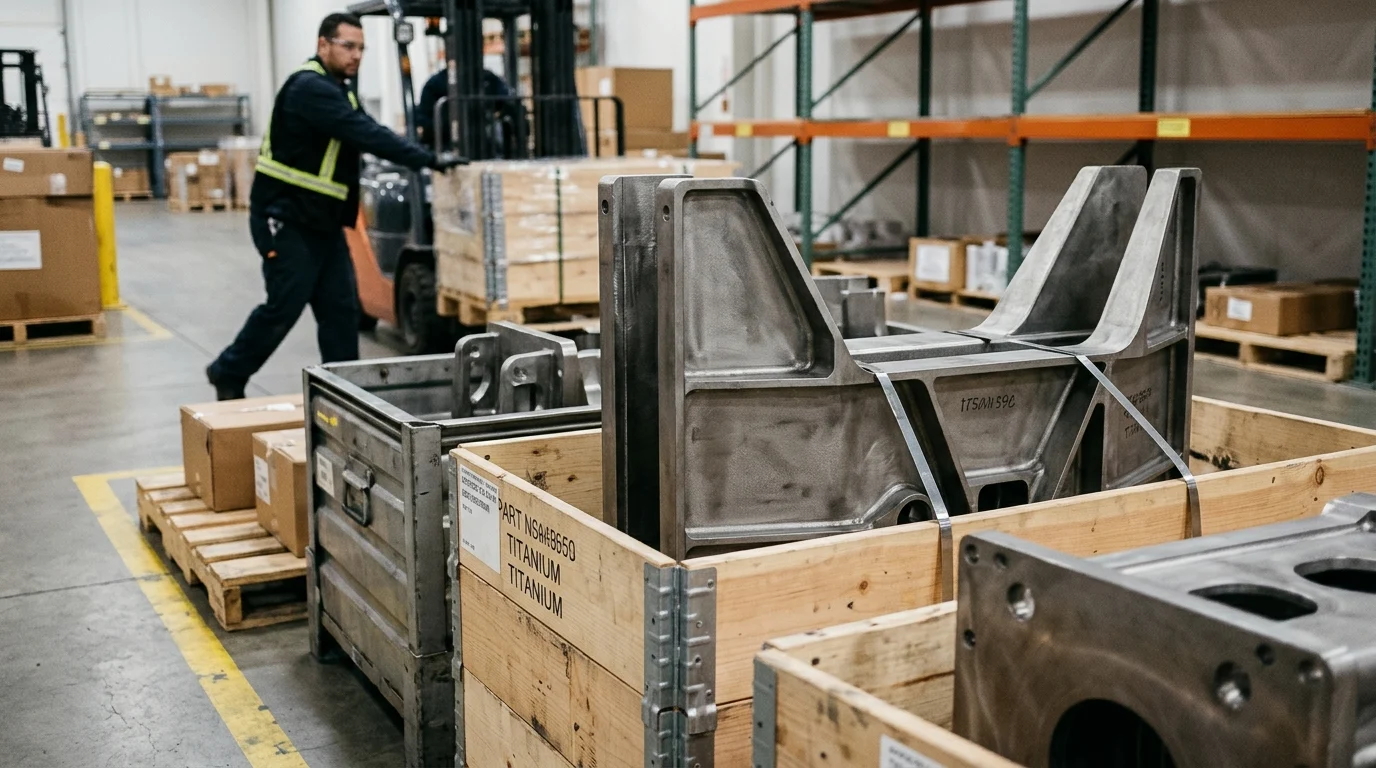
Defining a “thin” wall in titanium machining is highly context-dependent. While a 2.0 mm wall might be considered standard in aluminum, achieving the same thickness in titanium requires specialized tooling and toolpath strategies to hold typical precision tolerances of ±0.025 mm to ±0.050 mm. Pushing the boundaries below 1.0 mm demands an intimate understanding of how material properties and part geometry interact with the machining environment.
Establishing realistic limits during the design phase prevents costly manufacturing iterations. Engineers must recognize that theoretical minimums are often constrained by the physical realities of workholding, tool pressure, and the specific titanium grade selected.
How alloy, geometry, and process affect minimum wall thickness
The selected titanium alloy significantly influences the achievable minimum wall thickness. Commercially Pure (CP) Titanium (Grades 1-4) is softer and more ductile, making it prone to tearing and smearing if walls are machined too thin. In contrast, Grade 5 (Ti-6Al-4V) possesses a higher ultimate tensile strength (typically over 900 MPa), which provides better resistance to cutting forces, theoretically allowing for thinner functional walls. However, its lower thermal conductivity (around 6.7 W/m·K) traps heat at the cutting edge, inducing thermal distortion in thin sections and reducing tool life by up to 75% if coolant delivery is suboptimal.
Geometry and process capabilities also dictate limits. A 0.5 mm wall that is 5 mm tall is highly machinable, but a 0.5 mm wall that is 25 mm tall will almost certainly deflect beyond acceptable tolerance bands using standard 3-axis milling. Advanced 5-axis machining centers combined with specialized trochoidal milling toolpaths can reduce radial engagement, thereby lowering the cutting forces and allowing for thinner, deeper geometries.
Recommended wall thickness ranges by application
To guide the DFM process, it is useful to establish baseline recommendations based on the intended application and the typical manufacturing capabilities available at aerospace-grade machine shops. The table below outlines practical wall thickness limits, maximum recommended depth-to-thickness ratios, and typical tolerance bands to ensure high-yield production.
| Application Sector | Recommended Min Wall Thickness | Max Depth-to-Thickness Ratio | Typical Tolerance (mm) | Primary Limiting Factor |
|---|---|---|---|---|
| Aerospace Structural | 1.2 mm – 1.5 mm | 12:1 | ±0.050 | Rigidity under high-speed milling |
| Medical Enclosures | 0.3 mm – 0.5 mm | 8:1 | ±0.025 | Thermal distortion and springback |
| Semiconductor Components | 0.8 mm – 1.0 mm | 10:1 | ±0.015 | Vacuum tolerance and flatness |
| High-Pressure Fluid Manifolds | 2.0 mm – 2.5 mm | 15:1 | ±0.100 | Internal burst pressure limits |
Adhering to these ranges ensures that parts can be machined using standard high-performance carbide tooling without requiring exotic workholding solutions like low-melting-point alloy encapsulation, which drastically increases per-part costs by $150 to $400 depending on volume.
How to Predict and Control Wall Deflection
Wall deflection is the most pervasive mode of failure when machining thin titanium components. Because titanium’s yield strength (approx. 880 MPa for Grade 5) is high relative to its Young’s modulus (110-114 GPa), the material behaves like a stiff spring. Under the pressure of a cutting tool, the thin wall bows away from the cutter.
When the tool passes, the wall springs back to its original position. This results in a dimensional undersize on the pocket or an oversize on the wall thickness, often characterized by a tapered profile where the top of the wall is thicker than the base. Predicting and controlling this phenomenon is essential for maintaining tolerances tighter than ±0.05 mm.
Main drivers of deflection in thin titanium walls
Three primary drivers cause deflection in thin titanium walls: radial cutting forces, thermal expansion, and the release of residual stresses. Radial forces are generated by the end mill pressing against the side of the wall. If the wall lacks sufficient rigidity, it yields elastically. The deeper the pocket, the longer the lever arm, magnifying the deflection at the top edge of the wall.
Thermal expansion complicates this further. Because titanium is a poor conductor of heat, the energy generated by the shearing action is absorbed primarily by the cutting tool and the workpiece surface. In a wall thinner than 1.0 mm, this localized heat causes rapid, asymmetrical thermal expansion (approx. 8.6 µm/m·°C for Grade 5), causing the wall to warp mid-cut. Finally, raw titanium billets contain internal residual stresses from the forging and rolling processes. As material is removed to form a thin wall, these stresses are unevenly relieved, causing the entire component to bow or twist.
Common deflection risks and design controls
The most common risk associated with deflection is the inability to hold perpendicularity and thickness tolerances along the Z-axis. To combat this, designers must implement specific controls early in the CAD phase. One highly effective control is limiting continuous unsupported spans to under 40 mm. If a design requires a longer wall, integrating subtle buttresses or varying the wall thickness with a draft angle (even as small as 0.5 to 1.0 degrees) can exponentially increase stiffness by 15–25%.
Another design control is the specification of symmetric pocketing. By ensuring that material is removed equally from both sides of a central thin wall, the residual stresses released during machining balance each other out, keeping the wall plumb. In extreme cases where walls must be under 0.5 mm, designers should include sacrificial support ribs in the CAD model. These ribs stabilize the part during the majority of the roughing and semi-finishing operations and are only machined away in the final, low-force finishing pass.
Machining DFM Rules for Better Quality
Effective DFM for titanium machining is not just about modifying the design to make it possible to build; it is about modifying the design to make it stable, predictable, and economical. Every sharp corner or abrupt transition acts as a stress concentration and dictates the size of the cutting tool that can be used.
By tailoring the geometry to accommodate larger, more rigid tooling and smoother toolpaths, engineers can drastically reduce the cutting pressures that cause deflection and chatter, resulting in superior surface finishes (typically Ra 0.8 µm to 1.6 µm) and dimensional accuracy.
Best practices for radii, corner relief, and transitions
Internal radii are critical in thin-wall titanium design. A common mistake is specifying a corner radius that exactly matches the radius of the intended end mill. For example, using a 3.0 mm radius corner with a 6.0 mm diameter tool forces the tool into a 90-degree engagement, spiking radial loads and causing immediate chatter. Best practice dictates that corner radii should be at least 1.2 times the tool radius, which reduces radial engagement loads by 20–30%. Therefore, specifying a minimum internal radius of R > 3.6 mm allows a 6.0 mm tool to maintain a continuous, fluid motion through the corner.
Floor radii (the transition between the wall and the floor of a pocket) should also be maximized. A minimum floor radius of R > 1.5 mm is recommended, though R > 3.0 mm is ideal for pockets deeper than 20 mm. This thicker cross-section at the base acts as a rigid foundation for the thin wall above it. Furthermore, abrupt step-downs in wall thickness should be avoided. Replacing a sharp 90-degree step with a tapered transition of 5 to 10 degrees distributes the mechanical load and prevents localized tool pressure spikes.
How roughing, stress relief, and finishing reduce distortion
While process engineering is typically handled by the machinist, the designer must understand how the part will be manufactured to design it properly. Thin titanium walls are usually machined using a “waterline” or stepped approach. Roughing passes remove the bulk of the material, but they induce significant stress and heat. To counteract this, DFM guidelines suggest leaving a uniform 0.2 mm to 0.5 mm of stock material on the walls during roughing.
For highly critical, ultra-thin components, a thermal stress relief cycle is often required between roughing and finishing. The part is heated in an AMS 2801-compliant vacuum furnace (typically between 480°C and 595°C for 2 hours) to relax the residual stresses induced by the roughing cuts, a process that typically adds 12 to 24 hours to production lead times. By designing parts with uniform stock allowances and avoiding features that trap heat, the designer enables the machinist to execute a final, light finishing pass that gently shears away the remaining 0.2 mm of material without causing the wall to spring back.
Final Design Decisions and Trade-Offs
The final stages of designing a thin-walled titanium component require a careful evaluation of trade-offs. Removing material to save weight inevitably increases manufacturing complexity, machining time, and the risk of part rejection.
In titanium machining, the relationship between weight reduction and cost is not linear; it is exponential. Every 0.1 mm of titanium removed from a critical thin wall can drastically alter the required tooling strategies, potentially requiring custom vibration-damping tool holders or specialized coolant delivery systems that increase per-part costs by 1.5x to 3.0x.
When to add thickness, ribs, or support features
Engineers must objectively decide when a wall is simply too thin to be practical and when alternative structural features should be introduced. If a wall thickness analysis reveals that deflection will exceed the ±0.05 mm tolerance threshold, the primary solution is not always adding uniform thickness. Instead, designers should consider adding localized mass.
Integrating grid ribs, such as an isogrid or orthogrid pattern, is a highly efficient way to reinforce thin sections.
Key Takeaways
- Treat titanium walls near 2.0 mm as DFM-sensitive features and review tooling, fixturing, and tolerance targets before release.
- Avoid pocket depth-to-wall thickness ratios above 15:1 unless the design includes ribs, support features, or a validated machining strategy.
- Use ribs, isogrid patterns, or segmented spans to increase stiffness and reduce deflection in long thin-walled sections.
- Specify generous internal corner radii where possible because very small radii require smaller tools, slower feeds, and higher deflection risk.
- For Ti-6Al-4V, account for its approximately 114 GPa elastic modulus, which makes thin walls more prone to springback than steel.
- Validate sub-1.0 mm titanium walls early with the supplier, especially for aerospace, medical, and semiconductor components with tight tolerances.
Frequently Asked Questions
What is considered a thin wall in titanium machining?
It depends on geometry and tolerance, but titanium walls near 2.0 mm already require careful machining strategy. Walls below 1.0 mm are high-risk and typically need specialized tooling, staged machining, and close control of deflection.
Why do thin titanium walls deflect during machining?
Titanium has a relatively low elastic modulus compared with steel. Ti-6Al-4V is about 114 GPa, so thin sections can bend away from cutting forces and spring back, causing tolerance errors, chatter, or poor surface finish.
What depth-to-thickness ratio increases chatter risk?
A pocket depth greater than about 15 times the adjacent wall thickness, or a 15:1 ratio, significantly increases the risk of harmonic vibration and chatter during titanium machining.
How thin can titanium walls be for aerospace parts?
Aerospace titanium parts such as UAV brackets, satellite housings, and structural components may use walls around 1.2 mm, but this usually requires strong DFM review, rigid fixturing, and controlled toolpaths.
Can medical titanium components use sub-1 mm walls?
Yes. Some medical housings, implants, pacemaker components, and cranial plates may use 0.3–0.5 mm walls, but these dimensions require tight process control and should be validated with the manufacturer early.