Metal 3D Printing Tolerances: Ensuring Precision in Every Print
Introduction: The Critical Nature of Precision
In the dynamic world of metal 3D printing, achieving the desired precision is not just a goal—it’s a necessity. This necessity becomes even more pronounced when the smallest deviation in a printed component can lead to significant functional failures, particularly in critical applications such as aerospace and medical devices. This introduces a crucial question: How precise can metal 3D printing be? Understanding and optimizing these tolerances is not merely a matter of technical curiosity but a pivotal aspect of manufacturing strategy that affects the outcome of the final products.
Understanding Metal 3D Printing Tolerances
Metal 3D printing, renowned for its ability to produce complex geometries and customized parts rapidly, operates within a framework of specific tolerances that dictate the accuracy of each print. These tolerances are defined as the acceptable limit of dimensional variation, which ensures that parts fit together correctly in assemblies without requiring excessive modifications.
General Tolerances
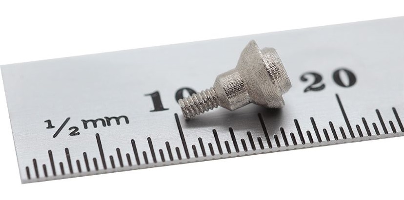
The standard tolerance for most metal 3D printing processes is approximately ±0.5 mm. However, this can vary significantly based on the complexity of the part and the technology used. Such a range is considered a starting point for understanding the capabilities of metal 3D printing.
Process-Specific Tolerances
- Direct Metal Laser Sintering (DMLS): DMLS is a precision-driven process that generally offers tolerances of ±0.005 inches (about ±0.127 mm) for the first inch, with an additional ±0.002 inches (approximately ±0.051 mm) for each subsequent inch. This precision makes DMLS ideal for applications requiring tight tolerances over smaller dimensions.
- Precision Metrics: Beyond DMLS, some metal 3D printing processes achieve even finer tolerances, approximately ±0.2% of the overall part size. For a 100 mm part, this could translate to a tolerance range of ±0.1 to ±0.2 mm, highlighting advanced capabilities in the field.
Metal 3D Printing Tolerance Table
| 3D Printing Technology | Tolerance Range | Notes |
|---|---|---|
| Direct Metal Laser Sintering (DMLS) | ±0.05 mm to ±0.1 mm | Suitable for most industrial applications |
| Electron Beam Melting (EBM) | ±0.1 mm to ±0.2 mm | Best for larger or thicker parts |
| Laser Metal Deposition (LMD) | ±0.1 mm to ±0.5 mm | Depends on the material and part design |
| Powder Bed Fusion (PBF) | ±0.2 mm to ±0.3 mm | Ideal for complex structures and fine features |
Tolerance Range: The listed tolerance ranges are average values based on specific printing technology and general printing conditions. Actual tolerances may vary due to factors such as design complexity, material choice, part size, and printing orientation.
Applicability: The appropriate printing technology should be chosen based on manufacturing needs, cost-effectiveness, and intended use. For example, precision medical devices or aerospace components may require stricter tolerance controls, while larger or non-structural parts may allow for broader tolerance ranges.
Influencing Factors
- Material Properties: Different metals respond differently to the heat of the printing process, exhibiting various degrees of shrinkage as they cool, which can significantly impact the final dimensions.
- Layer Thickness: The chosen layer thickness can affect tolerances; thicker layers might lead to increased deviations, emphasizing the need for careful setting adjustments.
- Design Complexity: The orientation and complexity of the design can also significantly impact tolerances. Complex geometries often require strategic design adjustments to ensure accuracy.
- Support Structures: Necessary for parts with overhanging features, support structures can affect both the surface finish and the dimensional accuracy of the final product. Proper design and placement of supports are crucial for achieving desired tolerances.
Material-Specific Considerations
The type of material used in metal 3D printing plays a critical role in the tolerances that can be achieved. For instance, titanium, known for its strength and lightweight properties, typically exhibits different shrinkage rates compared to stainless steel, affecting the tolerance levels that can be realistically achieved during printing.
The Role of Support Structures
Support structures are essential for creating accurate metal 3D printed parts, especially when dealing with complex designs and overhangs. These structures help maintain stability during the printing process, but they must be removed post-printing, which can sometimes lead to surface imperfections or slight deviations in measurements if not managed correctly.
Titanium 3D Printing Tolerances
Titanium, frequently used in industries requiring high strength-to-weight ratios, generally achieves tolerances around ±0.125 mm, depending on the printing setup and post-processing methods. This level of precision supports titanium’s prevalent use in aerospace and medical prosthetics.
Conclusion
Achieving precise tolerances in metal 3D printing is a multifaceted challenge that involves an in-depth understanding of material properties, printing technology, and design parameters. Each factor plays a significant role in how closely a printed part matches its digital model. By rigorously managing these elements, engineers and designers can harness the full potential of metal 3D printing to produce parts that not only fit their specifications but also perform optimally in their intended applications. This systematic approach ensures that the final products adhere closely to their intended dimensions, maximizing functionality and efficiency.