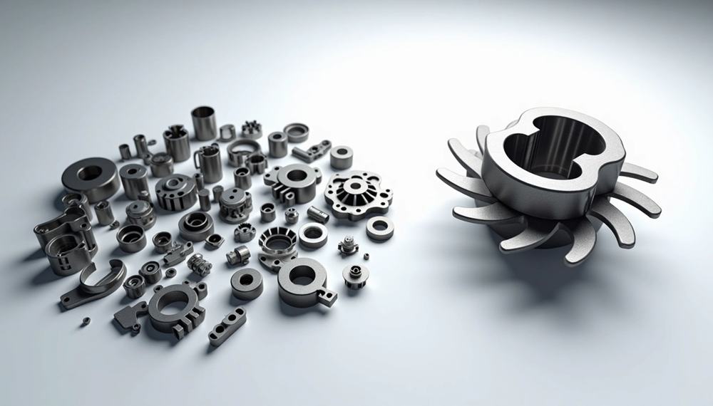
Design for additive manufacturing showed its true power in 2017 when GE Aviation transformed a helicopter engine’s design. The team reduced the part count from 900 to just 16 parts. This achievement explains what optimized design approaches can do with 3D printing technologies.
Designers have unprecedented freedom with additive manufacturing, and production costs often decrease. Traditional manufacturing has its limits, but additive manufacturing creates complex geometries with varying feature sizes. These range from tiny 0.0025 inches (0.0635mm) in SLA to 0.030 inches (0.762mm) in SLS processes. Different technologies need specific design rules. DMLS parts with thin walls must follow the 40:1 rule of height-to-wall thickness.
DFAM design for additive manufacturing aims to cut production time, costs, and failure risks while making components more functional and better quality. These technologies give designers more than just creative freedom. They make customization affordable, speed up iterations, cut material waste, and make supply chains simpler. The best results come from understanding everything in additive manufacturing design, from smallest possible features to material limitations.
This piece covers the core principles and techniques that help create optimized parts through additive manufacturing. Designers can use these revolutionary technologies’ full potential effectively.
Design Considerations for Additive Manufacturing Processes
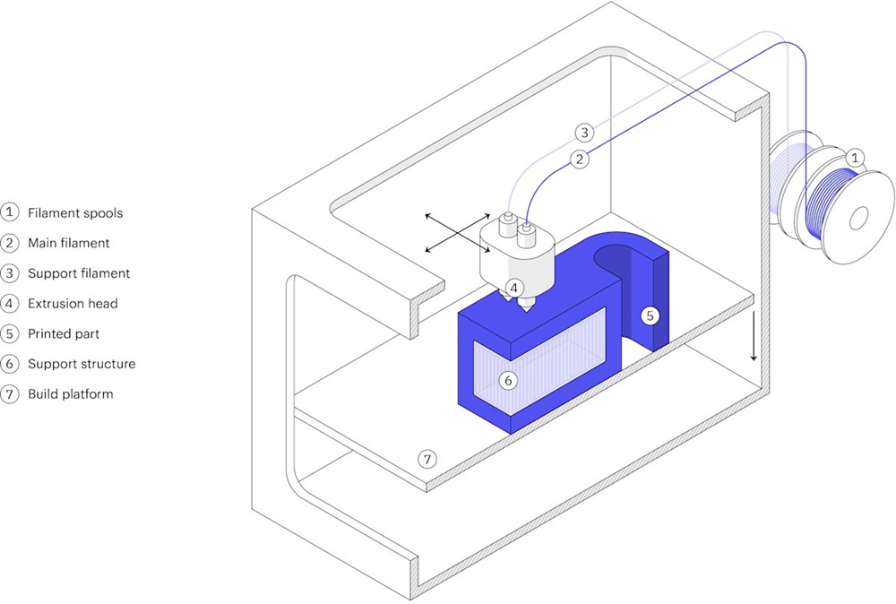
AM success depends on understanding process limits rather than seeing it as a solution for any shape. Each AM technology comes with specific shape constraints that affect build quality and how well parts work.
Matching Geometry to AM Process Capabilities
You need to know what shapes each process can handle to design parts that work. To name just one example, studies of Laser Metal Deposition (LMD) show that designers often don’t grasp the basic limits that can distort final parts. Research on sloped walls proves that every AM technology has a maximum angle before quality drops.
On top of that, recent studies have led to expert systems that spot risky shapes before production starts. A Python-based system uses build rules to suggest machine settings and design changes that improve part quality by a lot. This helps because shape limitations can really hurt builds, especially in wire arc Directed Energy Deposition (DED) processes.
Design rules that work for regular Material Extrusion (MEX) also work well with Continuous Fiber Reinforced MEX because these processes are similar.
Material-Specific Constraints in DMLS, SLA, and FDM
Different AM processes have unique material limits that shape design choices. FDM-printed ABS shows a Young’s modulus of 721 ± 115.07 MPa with tensile elongation at break of 26.35 ± 4.91%, while ASA is less stretchy at 729 ± 111.34 MPa and 22.84 ± 4.63%. These numbers show how materials change part performance.
SLA creates smoother, more detailed parts than FDM because its photopolymerization process bonds layers better. Yet SLA materials break more easily and work best for prototypes or short-term use. FDM works with common thermoplastics like ABS, PLA, and PETG, offering better durability but less detail.
Metal parts made with DMLS/SLM processes need supports for angles under 45° from the build platform. This is a big deal as it means that part orientation and support placement need careful planning.
Minimum Feature Size and Tolerance Guidelines
Smallest possible feature sizes vary widely between AM technologies:
| Process | Min. Wall Thickness | Min. Embossed Detail | Tolerance |
|---|---|---|---|
| FDM | 0.8 mm | 0.6 mm wide, 2 mm high | ± 0.5% (min: ± 0.5 mm) |
| SLA/DLP | 0.5 mm | 0.1 mm | ±0.15% (1-30 mm features) |
| SLS | 0.7 mm | 0.15 mm depth | ± 0.5% or 0.3 mm |
| DMLS/SLM | 0.4 mm | – | – |
| MJF | 0.5 mm | – | – |
Minimum hole sizes depend on the technology. SLS needs holes bigger than 1.5 mm to avoid trapped powder. FDM’s smallest holes are associated with nozzle size and layer height
Part size and complexity affect tolerances. SLA/DLP achieves ±0.15% for small features (1–30 mm) but goes up to ±0.3% for larger ones (81–150 mm), with a minimum of ±0.02 mm. FDM is less precise at ± 0.5% with a minimum of ± 0.5 mm.
Vertical pins need special attention. They should be at least 3 mm thick to print without warping, though 6 mm or larger works best.
Optimizing Geometry for Printability and Strength
The right geometric parameters are vital for successful additive manufacturing. These parameters do more than just make parts printable – they shape the part’s strength, determine build time, and control final quality.
Wall Thickness and Layer Height Trade-offs
Wall thickness is one of the most vital design choices you’ll make. SLA technology lets you print walls as thin as 0.2 mm, while FDM needs at least 0.8-1.2 mm thickness. SLS sits between these two, needing about 0.7 mm for vertical walls and 0.3 mm for horizontal features. Walls that are too thin might warp or crack later, so you need to think over both material properties and the part’s purpose.
Layer height and strength have an interesting relationship. Here’s a surprise – layer height doesn’t really affect part strength in FDM printing. This happens because thin layers create more extrusions but with smaller cross-sections, which balances out thicker layers that have fewer but bigger extrusions. In spite of that, layer height has a big effect on surface quality and print time. You can cut print time in half by jumping from 100 μm to 200 μm layers, but you’ll lose some surface finish quality.
Overhangs, Bridging, and Support Structure Minimization
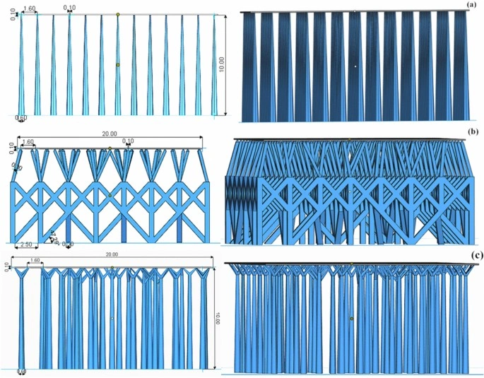
Support structures are needed when overhangs go beyond 45° from vertical in most additive processes. These supports use more material, take longer to print, and can mess up surface quality when removed. Here’s how to keep supports to a minimum:
- Point parts so overhangs stay under 45°
- Add chamfers between overhangs and base objects
- Design shapes that support themselves
- Use teardrop shapes instead of circles for internal channels
Bridging success depends on quick cooling and the right settings. Slower print speeds (20-30 mm/s) plus more cooling and lower temperatures help keep filament in shape across gaps. Triangle infill patterns work best for internal structures because they resist deformation better than other patterns.
Orientation for Load-Bearing and Surface Finish
The way you orient parts affects their strength, accuracy, and surface finish. FDM printed parts are stronger in some directions than others – they’re 4-5 times weaker along the Z-axis compared to the XY plane. This means load-bearing features should line up so stress runs along layers, not across them.
Surface finish changes a lot based on orientation. FDM’s upper surfaces look smoother because the extrusion tip finishes them, while supported surfaces often show marks after cleanup. SLA parts might need touch-ups where supports were attached to lower surfaces.
Smart part orientation can speed up printing since parts with less Z-height need fewer layers. This matters a lot in production, where printer time equals output. Part orientation drives more than 70% of additive manufacturing design rules, making it the key factor in getting both printable and reliable parts.
DfAM Techniques to Improve Functional Performance
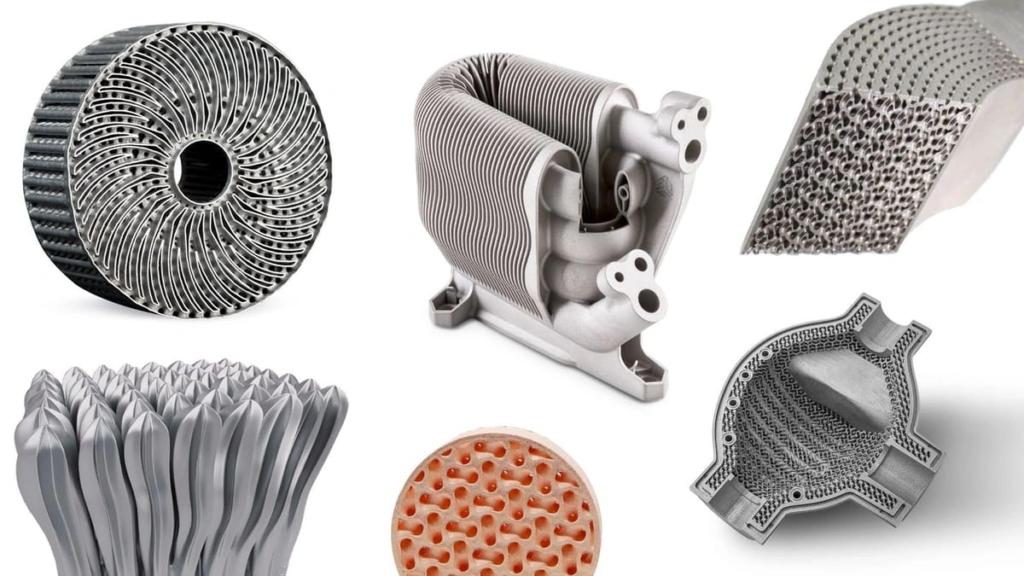
Advanced design for additive manufacturing (DfAM) techniques allows performance improvements that surpass traditional manufacturing methods. These approaches utilize AM’s unique capabilities to boost product functionality through considered design strategies.
Internal Channels for Thermal and Fluid Applications
Complex internal channels created through additive manufacturing boost thermal management systems by a lot. Direct metal laser sintering in turbine components provides design freedom to add sophisticated cooling schemes. Research shows that AM-built channel directions affect internal surface roughness, which impacts heat transfer and pressure loss. Engineers can employ this property to create heat exchangers with specific performance characteristics.
Notable applications include:
- Gas turbine components with variable cooling feature sizes
- Aerospace turbogenerators with conformal cooling channels that reduced operating temperature by 33%
- Fuel-cooled oil coolers with gyroid lattice cores, achieving 80% weight reduction yet a higher heat transfer coefficient
Surface Texturing for Ergonomics and Esthetics
Surface texturing through additive manufacturing combines improved functionality with visual appeal. Research from 33 studies has shown ergonomic applications mainly in medicine and assistive technologies. Surface textures can hide layer lines from the printing process while boosting product function.
Textured surfaces provide better grip friction for handles, improved stiffness without extra material, and optimized water and air flow characteristics. Custom ergonomic designs through AM reduce peak plantar pressure in medical applications by a lot.
Multi-Material Design for Functional Grading
Multi-material 3D printing creates functionally graded materials (FGMs) that represent a major advancement in component design. These materials show gradual transitions between different properties within a single part. Designers can combine hard and soft materials to create biomimetic structures with precise characteristics.
This approach allows different property regions—from rigidity to flexibility, thermal conductivity to electrical resistance. Applications range from prosthetics that combine soft TPU contact points with stiff carbon fiber structures to nuclear components with microstructural gradients that fight corrosion. Precise control of fusion processes creates high-quality, defect-free parts that work reliably in demanding environments.
Reducing Cost and Time with Smart Design Choices
Design choices in additive manufacturing affect production costs through less material use, quicker builds, and simplified processes. These approaches can save money significantly while you retain control over part functionality.
Part Consolidation to Eliminate Assembly
Merging multiple components into a single printed part offers a powerful way to cut costs in additive manufacturing. General Electric’s fuel nozzle for the CFM LEAP aircraft engine shows this perfectly – they united 20 separate parts into one component. The result was 25% less weight and five times longer part life. This method eliminates assembly work, needs less inventory, and removes quality checks during production.
Part consolidation makes parts more reliable by reducing weak points between components. 3D printing a single part often costs less and takes less time than making multiple pieces traditionally and joining them later. Some cases show production costs dropping by up to 95%.
Topology Optimization to Minimize Material Use
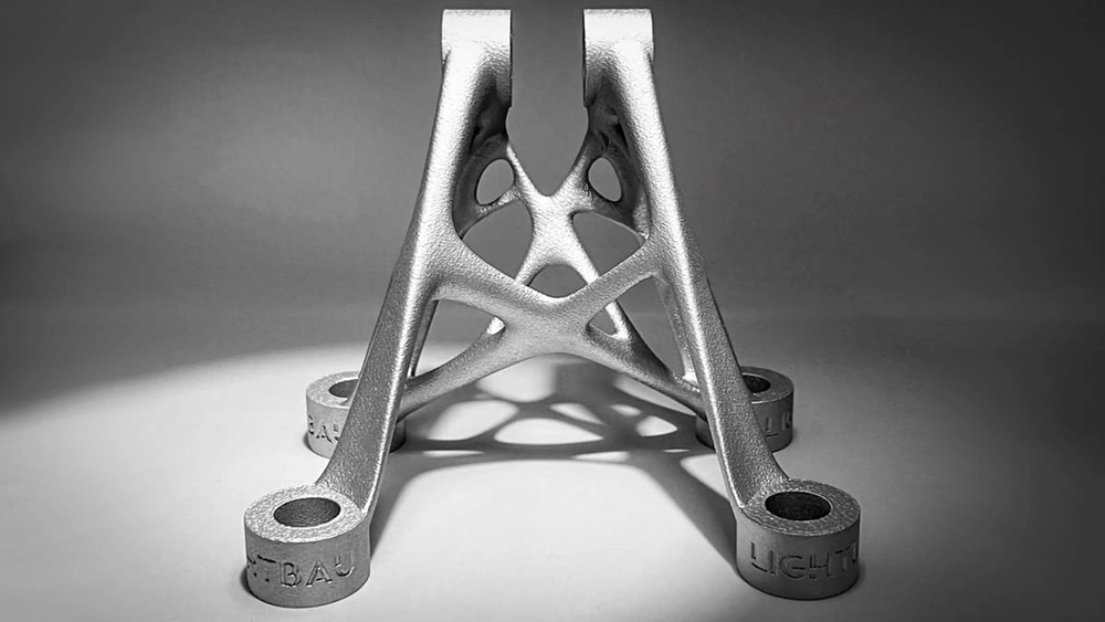
Topology optimization algorithms place material only where needed structurally. This creates strong yet lightweight components. The approach uses 35-65% less material than traditional manufacturing methods. Optimized designs need less build time, which cuts machine costs.
The A320 nacelle hinge bracket demonstrates this well. After redesign for additive manufacturing, its weight dropped from 918g to 326g. Lighter parts bring benefits throughout their lifecycle – shipping costs less, fuel efficiency increases, and packaging becomes easier.
Support-Free Design for Faster Builds
Support structures waste material and time, and removing them takes work. Support-free designs want to minimize or remove these non-functional elements. The practical steps include:
- Designing self-supporting overhangs below critical angles
- Using teardrop-shaped holes instead of circular ones to avoid internal supports
- Creating sub-assemblies printed flat on build plates requires fewer supports
Designers can now print bridges and overhangs at lower angles without losing part quality thanks to innovative parameter adjustments and software. One case showed that removing internal supports cut production costs by 35%.
Smart design combined with up-to-the-minute process control technologies like Smart Fusion can cut support structure needs by up to 75%. This improves build consistency and uses fewer resources.
Automation and Software in Additive Manufacturing Design
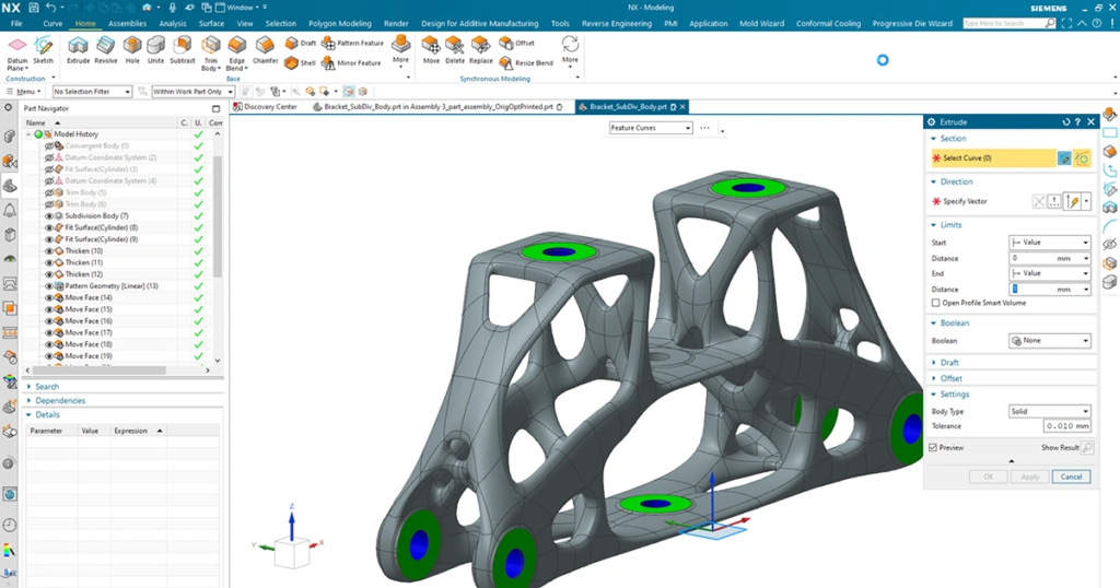
Modern software tools are transforming additive manufacturing workflows. Computational approaches now boost design capabilities well beyond what manual methods can achieve.
Generative Design Algorithms for Complex Parts
Generative design uses advanced algorithms and AI to discover countless design possibilities within user-defined constraints. Traditional CAD requires designers to create models from scratch. However, generative design starts with parameters and lets AI create optimized solutions automatically. This method places material exactly where needed and typically cuts weight by 35-65%. Engineers can now assess hundreds or thousands of design options at once, which significantly reduces development time.
Design Automation for Personalized Products
Mass customization has turned completely digital through automated design processes. Manufacturers can now overcome barriers to tailored production by making their manual workflows digital. This automation powers healthcare applications like custom surgical implants and prosthetics that use patient’s specific data. Smart design algorithms adjust parameters to match individual needs. The result is customized products that need 80% less engineering time and deliver 20% improved performance.
Simulation Tools for Predicting Print Outcomes
Simulation technologies let engineers test virtually before production and minimize expensive iterations. Advanced predictive models like gradient boosting regression now achieve prediction accuracies up to 99.9% for process parameters and outcomes. These tools predict thermal performance, potential distortions, and structural integrity without physical prototypes. Engineers can verify designs before manufacturing through complex simulations of part behavior at different temperatures. This approach reduces the risks during market launch significantly.
Conclusion
Additive manufacturing is changing how engineers envision product development possibilities. This piece explores the foundations of successful design for additive manufacturing (DfAM) implementation.
Getting the best results depends on understanding process-specific constraints. Each technology—whether DMLS, SLA, or FDM—has its own limits for minimum feature sizes, overhangs, and material properties. Engineers need to match their geometric requirements to the right manufacturing processes instead of seeing AM as a solution without bounds.
Design choices substantially affect both performance and economics. Wall thickness, part orientation, and support structure reduction play a direct role in build quality, mechanical properties, and production costs. Advanced techniques like internal channeling, surface texturing, and multi-material approaches help realize capabilities that traditional manufacturing can’t match.
Smart design strategies make additive manufacturing’s economic benefits clear. GE showed this by cutting helicopter engine components from 900 to just 16 parts. This eliminated assembly needs and boosted reliability. Topology optimization cuts material use by 35-65% and creates lightweight yet strong components.
Modern computational tools have pushed design possibilities way beyond manual methods. Engineers now use generative algorithms, design automation, and simulation software to test thousands of design variations at once. They can predict outcomes before actual production starts.
Additive manufacturing runs on the perfect mix of design freedom and process knowledge. These technologies offer amazing capabilities, but success comes from knowing both what’s possible and what isn’t. Companies that become skilled at these principles see soaring wins in performance, cost savings, and manufacturing efficiency. They’re not just changing how parts are made—they’re redefining what’s possible to create.
Key Takeaways
Master these essential principles to unlock additive manufacturing’s full potential for creating optimized, cost-effective parts with enhanced functionality.
• Match geometry to process capabilities – Each AM technology has specific constraints; FDM requires 0.8mm walls while SLA achieves 0.2mm precision • Design for 45-degree rule – Keep overhangs above 45° to minimize support structures, reducing material waste and post-processing time • Leverage part consolidation – Combine multiple components into single prints to eliminate assembly, reduce costs by up to 95%, and improve reliability • Apply topology optimization – Use algorithms to place material only where needed, achieving 35-65% weight reduction while maintaining strength • Orient parts strategically – Position load-bearing features parallel to layers for 4-5x stronger parts and optimize surface finish quality • Utilize generative design tools – AI-powered algorithms explore thousands of design variations automatically, reducing engineering time by 80% while boosting performance
When implemented correctly, these DfAM principles transform manufacturing economics by reducing material usage, eliminating assembly steps, and enabling complex geometries impossible with traditional methods.
FAQs
Q1. What are the key advantages of design for additive manufacturing (DfAM)? Design for additive manufacturing offers significant advantages including design freedom, low-cost customization, faster iterations, reduced material waste, and simplified supply chains. It enables the creation of complex geometries and consolidation of multiple parts into single components, potentially lowering production costs and improving functionality.
Q2. How does part orientation affect the strength and quality of 3D printed objects? Part orientation significantly impacts strength, accuracy, and surface finish. Most FDM printed parts show 4-5 times less tensile strength along the Z-axis compared to the XY plane. Orienting load-bearing features parallel to layers rather than across them can improve strength. Surface finish also varies with orientation, with upper surfaces in FDM typically appearing smoother.
Q3. What is topology optimization and how does it benefit additive manufacturing? Topology optimization is an algorithmic approach that distributes material only where structurally necessary, creating lightweight yet strong components. It typically reduces material usage by 35-65% compared to traditionally manufactured parts. This not only saves on material costs but also decreases build time, directly lowering machine costs and improving overall efficiency.
Q4. How can internal channels improve the performance of 3D printed parts? Internal channels, made possible by additive manufacturing, can significantly enhance thermal management and fluid applications. They allow for the creation of sophisticated cooling schemes in components like turbines, improving heat transfer and reducing operating temperatures. This capability has led to innovations in aerospace, such as turbogenerators with conformal cooling channels that reduced operating temperature by 33%.
Q5. What role do simulation tools play in additive manufacturing design? Simulation tools are crucial for predicting print outcomes before physical production begins. They enable virtual testing of thermal performance, potential distortions, and structural integrity, minimizing costly iterations. Advanced predictive models can achieve accuracies approaching 99.9% for process parameters and outcomes, helping engineers verify designs and reduce market launch risks.

