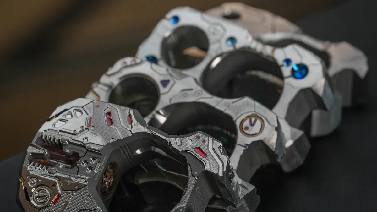
Titanium’s exceptional properties drive its increasing adoption in additive manufacturing. Industries such as aerospace, medical, and automotive leverage titanium 3D printed parts for high-performance components, like lighter brake calipers for supercars. Designing these parts effectively requires optimizing geometry for superior strength-to-weight ratios. Engineers must also implement strategies to minimize support structures and manage thermal stress effectively. This ensures seamless post-processing compatibility, crucial for the rapidly growing global 3D printing metal market, where titanium holds the largest segment share.
Key Takeaways
- Titanium is great for 3D printing because it is strong, light, and safe for medical use. It also resists rust well.
- Design parts carefully to make them light and strong. Use special software to remove extra material and create unique shapes.
- Lattice structures help make parts lighter and absorb shock better. They are good for aerospace and medical uses.
- Always follow rules for wall thickness and small details. This helps prevent printing mistakes and makes parts strong.
- Manage heat during printing to stop parts from bending or cracking. Use special designs to cool parts evenly.
- Plan for cleaning and finishing parts after printing. This makes sure they look good and work correctly.
- Save money by using less material and printing faster. Design parts so they need less cleaning after printing.
- Understand that 3D printed titanium can be stronger in one direction. Test parts to make sure they work as expected.
Understanding Titanium for Additive Manufacturing of 3D Printed Parts
Why Choose Titanium for 3D Printing?
High Strength-to-Weight Ratio Benefits
Titanium offers a superior strength-to-weight ratio, making it ideal for demanding applications. This enables complex designs impractical with heavier materials. Titanium demonstrates exceptional mechanical performance, including high Young’s Modulus (nearly 500 GPa) and Shear Modulus. These properties ensure stiffness, rigidity, and resistance to torsion and deformation. Titanium alloys also exhibit excellent fatigue resistance, enduring repeated stress cycles vital for dynamic applications.
3D printed titanium, especially Ti6Al4V, is recognized for its high strength-to-weight ratio. It achieves tensile strengths over 1600 megapascals, making it one of the strongest 3D-printed metals available. This unique microstructure makes it a preferred choice where weight reduction without compromising strength is crucial, such as in aerospace and automotive.
Biocompatibility for Medical Applications
Titanium is highly biocompatible. The human body tolerates it well without adverse reactions. This makes titanium an excellent choice for medical implants, surgical instruments, and prosthetics.
Corrosion Resistance in Harsh Environments
Titanium exhibits outstanding corrosion resistance. It forms a passive oxide layer that protects it from aggressive chemicals and environments. This makes it suitable for marine, chemical processing, and other harsh industrial applications.
Common Titanium Alloys for 3D Printed Parts
Ti6Al4V (Grade 5) Characteristics
Ti6Al4V, or Grade 5 titanium, is the most widely used titanium alloy in additive manufacturing. It contains 6% aluminum and 4% vanadium. This alloy offers an excellent balance of strength, ductility, and fracture toughness. It is a workhorse material for aerospace, automotive, and medical industries.
Ti6Al4V ELI (Extra Low Interstitials) Applications
Ti6Al4V ELI is a variant of Ti6Al4V with extra low interstitial elements. This improves the alloy’s ductility and fracture toughness, especially at cryogenic temperatures. It is primarily used in biomedical implants and applications requiring enhanced toughness.
Other Specialized Titanium Alloys
Other specialized titanium alloys exist for specific applications. These include Ti-6Al-2Sn-4Zr-2Mo for high-temperature uses. The choice depends on the final part’s performance requirements.
Challenges in 3D Printing Titanium Parts
High Material and Processing Costs
Titanium 3D printing is a premium technology with high costs. Titanium powder can cost several hundred dollars per kilogram. High-end equipment, like DMLS or EBM printers, costs hundreds of thousands of dollars and requires controlled environments. Post-processing steps further increase the overall cost. However, 3D printing eliminates expensive tooling, making it cost-effective for low-volume production.
| Cost Factor | Titanium 3D Printing | Traditional Manufacturing |
|---|---|---|
| Raw Material Cost (per kg) | USD 300-600 | USD 100-150 |
| Buy-to-Fly Ratio | 3:1 to 12:1 | 12:1 to 25:1 |
| Material Utilization Rate | >95% | 30-70% |
| Tooling Costs | Eliminated | Required |
Critical Thermal Management Requirements
Rapid heating and cooling cycles during 3D printing create high thermal gradients. This generates internal residual stress. This stress can cause part distortion, cracking, or build failure. Uneven heating and cooling also lead to thermal distortion, affecting dimensional accuracy.
Reactivity and Oxidation Concerns
Titanium is highly reactive at high temperatures. It absorbs oxygen, nitrogen, or hydrogen, causing embrittlement and reduced ductility. This leads to poor mechanical performance. Therefore, 3D printing titanium requires inert atmospheres to prevent oxidation.
Residual Stress and Distortion Issues
Residual stress is a significant challenge. It arises from rapid thermal cycles inherent in additive manufacturing. This stress can lead to warpage, cracking, and dimensional inaccuracies in the final Titanium 3D Printed Parts. Design strategies and post-processing heat treatments are crucial to mitigate these issues.
Optimizing Geometry for Titanium 3D Printed Parts (DFAM)
Topology Optimization for Performance
Maximizing Strength-to-Weight
Topology optimization significantly enhances the lightweight properties of titanium additive manufacturing. Engineers use specialized software to define requirements such as load and stiffness constraints. The software then optimizes the initial design by removing unnecessary material. This process results in a lighter yet strong component. These topologically optimized designs are often only manufacturable using additive manufacturing technologies. This is particularly valuable in aerospace for weight savings and improved aircraft performance.
Topology optimization is an advanced structural design methodology. It generates innovative lightweight and high-performance configurations. These configurations are difficult to achieve with traditional methods. When integrated with additive manufacturing, which builds structures layer-by-layer and offers design freedom for complex components, it maximizes their combined advantages and potential. This leads to wide application prospects in modern manufacturing.
“Overall, this project shows what modern structural optimization in combination with additive manufacturing processes can already achieve today. Additive manufacturing is convincing here due to its design freedom. It enables the realization of complex geometries and offers the possibility of using resources very efficiently. The potential of 3D printing technology to completely rethink products and overcome the limits of conventional manufacturing methods is enormous,” concludes Florian Pfaff.
Reducing Material Consumption
Topology optimization is a mathematical approach. It uses the finite element method to iteratively optimize the arrangement of materials within a given design space. It considers relevant load cases and boundary conditions to achieve ideal performance. This effectively determines where material is necessary and where it can be omitted for optimal structural efficiency. This process is followed by shape optimization to reduce local stress peaks, improving component service life. The final optimized design then integrates into a usable CAD model for practical application. This method drastically reduces the amount of raw material needed.
| Manufacturing Method | Buy-to-Fly Ratio (Titanium Aircraft Parts) |
|---|---|
| Traditional | 12:1 to 25:1 |
| Metal 3D Printing | 3:1 to 12:1 |
The table above illustrates how metal 3D printing, especially with topology optimization, dramatically improves the buy-to-fly ratio compared to traditional manufacturing. This means less raw material is purchased for the final part, leading to significant cost savings and reduced waste.
Generating Organic Forms
Topology optimization naturally produces organic, biomimetic forms. These shapes often resemble structures found in nature, like bones or tree branches. Such complex geometries are impossible to create with conventional manufacturing techniques. Additive manufacturing’s layer-by-layer process makes these intricate designs feasible. This design freedom allows engineers to push the boundaries of performance and aesthetics.
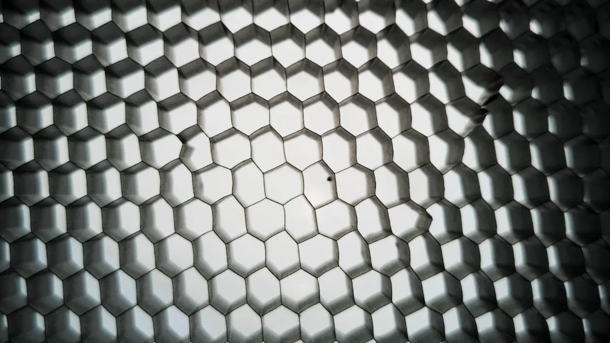
Lattice Structures for Lightweight Titanium 3D Printed Parts
Types of Lattice Geometries
Lattice structures consist of repeating unit cells. These cells form an open, porous network. Common types include:
- Strut-based lattices: These use interconnected beams or struts, like cubic, octet, or body-centered cubic (BCC) structures.
- Surface-based lattices: These use minimal surfaces, such as gyroids or diamond structures, offering smooth transitions and often better flow properties.
- Hybrid lattices: These combine elements of both strut and surface-based designs.
Design Considerations for Lattices
Designing effective lattice structures requires careful consideration. Engineers must choose the appropriate unit cell type based on the application’s mechanical requirements. Factors like strut diameter, cell size, and relative density directly influence the lattice’s properties. Simulation tools help predict performance and optimize the lattice design. Proper design ensures manufacturability and prevents issues like trapped powder.
Impact on Mechanical Properties
Lattice structures significantly reduce the amount of material used by removing non-critical areas. This leads to substantial weight reduction. This is particularly beneficial in aerospace and automotive applications for fuel efficiency. In medical cases, it improves patient recovery time. The reduction in material usage also translates to cost savings, especially for expensive materials like titanium.
Lattice materials are highly valued in engineering disciplines such as automotive and aerospace. They offer a high strength-to-weight ratio and enhanced mechanical energy absorption. They also find applications in the biomechanical field as bone substitutes.
Key benefits of lattice structures include:
- Reduced part cost: Less material usage, especially for expensive materials like titanium, makes parts cheaper without sacrificing structural integrity.
- Improved strength-to-weight ratio: Parts with lattice structures can achieve unparalleled strength-to-weight ratios. This is critical for minimizing mass in automotive and aerospace applications.
- Shock absorption: Lattice structures efficiently dissipate impact and shock loads due to their cell configuration. This allows the construction to flex and disburse energy.
- Osseointegration: In medical implants, lattice structures promote bone growth. This leads to stronger bonds with the patient’s bone structure.
These structures are ideal for creating lightweight structural parts without compromising strength. The additive manufacturing process minimizes waste, which is particularly important for expensive metals like titanium.
Wall Thickness and Feature Size for Titanium 3D Printed Parts
Minimum Wall Thickness Guidelines
For Titanium 3D Printed Parts, standard grade titanium requires a minimum wall thickness of 1mm. Performance-grade titanium can achieve walls as thin as 0.5mm. For optimal stability in critical load-bearing applications, a wall thickness of 2mm is recommended. Non-load-bearing components can utilize thinner wall sections and hollowing techniques. They must maintain the minimum recommended thickness to prevent print failures.
| Technology | Material | Minimum Wall Thickness (mm) |
|---|---|---|
| SLM | Titanium Alloy | 0.6-1.0 |
| Binder Jetting | Titanium/Tool Steel | 0.75-1.25 |
These guidelines help ensure successful prints and structural integrity.
Designing for Smallest Feature Resolution
Direct Metal Laser Sintering (DMLS) can produce details as small as 0.25mm. Recommended minimum feature sizes range from 0.15mm to 0.38mm, depending on the printer’s capabilities. Designers must consider these limitations when creating intricate features. Features below the minimum resolution may not print accurately or may fail during the build.
Best Practices for Robust Features
To ensure robust features, designers should:
- Avoid sharp corners: Incorporate fillets and radii to reduce stress concentrations.
- Ensure adequate support: Small, delicate features often require more support during printing.
- Consider orientation: Orienting the part strategically can improve the quality of fine features.
- Design for post-processing: Account for potential material removal during support cleanup or surface finishing.
Hollow Structures and Internal Channels in Titanium 3D Printed Parts
Designing for Internal Functionality
Designing hollow structures and internal channels significantly expands the functional capabilities of 3D printed components. Engineers can integrate complex internal geometries that traditional manufacturing methods cannot produce. These designs allow for optimized fluid flow, enhanced heat exchange, and substantial weight reduction. For example, internal cooling channels can precisely route coolant through critical areas of a part, improving thermal management. Similarly, intricate fluidic pathways can be designed for medical devices or chemical processing equipment. This design freedom enables the creation of multi-functional parts, consolidating several components into a single, optimized structure. This approach reduces assembly complexity and improves overall system performance.
Challenges of Powder Removal
The presence of internal channels introduces a significant challenge: removing unfused powder. In powder bed fusion processes, the build chamber fills with fine metal powder. The laser selectively melts specific areas. Unmelted powder surrounds the printed part, including within any internal cavities. Removing this trapped powder from intricate internal geometries proves difficult. If powder remains, it adds unwanted weight, can interfere with fluid flow, or even compromise the part’s mechanical properties. Accessing these internal spaces for cleaning often requires specialized tools or additional design features. Inadequate powder removal can lead to performance issues or even part failure in critical applications.
Strategies for Self-Supporting Channels
Designers employ several strategies to mitigate the challenge of powder removal and minimize the need for internal supports. One effective approach involves designing channels to be self-supporting. This means orienting and shaping the channels so they do not require additional support structures during the printing process.
- Optimized Cross-Sections: For internal channels larger than Ø 8 mm, diamond or tear-drop cross-sections are preferred over circular ones. These shapes inherently reduce the need for internal supports, as their angled walls can support themselves during the build. Circular channels, especially larger ones, often require extensive internal supports, making powder removal extremely difficult.
- Angled Channels: Orienting channels with a slight upward angle (typically 45 degrees or more from the horizontal) allows the channel roof to be self-supporting. This prevents collapse during printing.
- Access Holes: Incorporating strategically placed access holes allows for easier removal of trapped powder. Designers must consider the size and location of these holes to ensure effective cleaning without compromising structural integrity.
- Gravity-Assisted Drainage: Designing channels with a slight incline can facilitate gravity-assisted powder drainage after the build. This helps clear loose powder from the internal pathways.
- Sacrificial Structures: In some cases, designers might use sacrificial support structures within channels. These structures are designed to be easily broken up or dissolved during post-processing, allowing for powder removal. However, the primary goal for Titanium 3D Printed Parts remains to minimize or eliminate internal supports through clever design.
Minimizing and Managing Support Structures for Titanium 3D Printed Parts
Overhang Angles and Critical Limits
Understanding Self-Supporting Angles
Designers must understand self-supporting angles to minimize support structures in titanium 3D printing. Features can be self-supporting if their angle is not less than 45° relative to the build plate. Structures generally require support when overhang angles are less than 40-45°. However, some Ti6Al4V alloys can be printed without supports for angles up to 30°. Overhanging surfaces with angles between 30° and 45° are often considered self-supported.
Impact of Overhangs on Surface Quality
Overhangs significantly affect surface quality. Features printed with angles below 45° typically result in rougher surfaces. Steeper angles, conversely, yield smoother finishes. The “staircasing” effect, inherent in layer-by-layer fabrication, impacts the surface finish of slanted or curved surfaces. Partially melted powder particles can also adhere to surfaces, contributing to roughness.
Material-Specific Angle Considerations
Different titanium alloys and printing processes may have slightly varied critical angles. Designers should consult specific machine and material guidelines. This ensures optimal results and minimizes the need for extensive post-processing.
Strategic Part Orientation for Titanium 3D Printed Parts
Reducing Support Volume
Strategic part orientation significantly impacts the volume of necessary support structures. Optimizing the orientation can reduce support material, which saves costs and build time. For instance, printing a part vertically (upside-down) might allow for more parts in a single build and reduce the overall time per part, even if the total build time increases.
| Orientation | Number of Parts | Build Time (hours) | Time per Part (hours) |
|---|---|---|---|
| On its side | 10 | ~40 | ~4 |
| Vertically (upside-down) | 24 | ~85 | ~3.5 |
Optimizing Surface Finish
Part orientation also influences surface finish. Upward-facing surfaces generally have the best quality. Surfaces in contact with supports or the print bed may show marks or a different texture. Printing parts at an angle can help balance layer stepping and achieve a more uniform surface finish. Reorienting a part to make sloped surfaces vertical or horizontal can mitigate staircasing.
Minimizing Build Time
Part orientation significantly impacts build time. A horizontal cylinder prints faster than a vertical one due to a reduced number of layers. Strategic orientation can also minimize the need for support structures, which add time and cost. Optimization systems can reduce both residual stress and support structure volume by finding the best build orientation for Titanium 3D Printed Parts.
Designing for Easy Support Removal
Accessibility for Post-Processing Tools
Designers must consider the accessibility of support structures for removal. Complex internal supports or those in tight spaces can be extremely difficult to remove. This increases post-processing time and cost.
Minimizing Contact Area
Minimizing the contact area between the support and the part reduces the effort required for removal. It also lessens the likelihood of surface damage. Using point or line contacts instead of solid blocks can be effective.
Preventing Surface Damage
Supports leave marks upon removal. Designers should place supports on non-critical surfaces or areas that will undergo further machining. This prevents damage to functional or aesthetic surfaces.
Internal Supports for Titanium 3D Printed Parts
When Internal Supports are Necessary
Internal supports become essential for titanium 3D printed parts when designs feature complex geometries. These geometries include significant overhangs or internal cavities. Internal supports are necessary primarily for overhangs exceeding 45 degrees. They prevent collapse and ensure proper formation during the build process. Without these supports, the molten metal can sag, leading to part failure or poor surface quality. Optimizing part orientation is crucial to minimize support usage and enhance print quality. Furthermore, thermal management strategies, including optimized support structures and controlled cooling cycles, are vital. These strategies combat warping due to high thermal gradients during the printing process.
Design for Removability
Designing internal supports for removability is a critical consideration. Engineers must ensure accessibility for support removal, potentially by designing access ports. These ports allow tools to reach and extract the support material. For internal channels and cavities, designers should aim for self-supporting shapes like teardrops or diamonds. These shapes eliminate the need for internal supports, which are extremely difficult or impossible to remove once printed. Including drain holes or access points also facilitates the removal of unfused powder from internal cavities. This prevents trapped powder from compromising part functionality or adding unwanted weight. Designing critical surfaces to be self-supporting also avoids rough finishes from supported areas.
Sacrificial Support Strategies
Sacrificial support strategies involve designing supports that are easily removed or dissolved after printing. These supports are often minimal in contact area, making them easier to break away. For instance, designers can use thin, lattice-like support structures that fracture easily. In some advanced applications, engineers might design supports from a different material that can be chemically dissolved. This method is less common for titanium but highlights the principle. The goal is to provide temporary structural integrity during the build. Then, the supports disappear without damaging the final part. This approach minimizes post-processing effort and reduces the risk of surface imperfections. It also ensures the integrity of complex internal features.
Thermal Management and Stress Reduction in Titanium 3D Printed Parts
Heat Dissipation in Design
Designing for Uniform Cooling
Achieving uniform cooling is crucial for successful titanium 3D printing. Designers must consider how heat dissipates throughout the part during the build process. Conformal cooling channels, for example, precisely follow part contours. These channels, like those in cylinder liners or high-heat zones, create highly efficient cooling systems. This design approach improves thermal management, reduces thermal stress, and enhances durability. It directly addresses hot spots during the build process by facilitating heat removal.
Preventing Hot Spots
Preventing hot spots is essential to avoid premature cracking and thermal fatigue. Advanced thermal management, specifically through conformal cooling, effectively prevents these issues. Designers can also minimize support structures. Strategically orienting the part, designing gradual transitions, and utilizing self-supporting angles (e.g., greater than 45 degrees) reduces the need for supports. This helps manage thermal stress during the build, reducing the risk of warping and localized heat accumulation. Designing internal channels with diamond or teardrop cross-sections instead of circular ones also contributes to self-support, further preventing hot spots.
Impact of Geometry on Heat Flow
Part geometry significantly impacts heat flow. Large, flat surfaces and complex internal structures can create localized stresses and areas prone to warping or hot spots. The thermal conductivity and expansion coefficients of materials like Ti-6Al-4V also influence how heat dissipates and how melt pools behave during printing. Properly designed support structures are crucial for anchoring the part and managing thermal stress. Build orientation also affects support requirements and thermal gradients, influencing the distribution of heat during the printing process.
Mitigating Warpage and Distortion
Understanding Residual Stress Formation
Residual stress is a major challenge in titanium 3D printing. It forms due to the rapid heating and cooling cycles inherent in additive manufacturing. This creates high thermal gradients within the material. These stresses can lead to warpage, cracking, and dimensional inaccuracies in the final parts.
Design Features to Reduce Stress
Designers can incorporate several features to reduce residual stress. Printing with short track lengths minimizes residual stresses and distortion. Controlling deposition patterns also significantly affects stresses and distortions. Furthermore, the substrate preheat temperature is a highly influential variable in reducing residual stresses. These design and process choices help manage the thermal effects.
Role of Build Plate Temperature
The build plate temperature plays a critical role in mitigating warpage. A heated build plate reduces the temperature difference between the printed layer and the underlying material. This minimizes thermal shock and helps to control residual stress formation. Maintaining an optimal build plate temperature is essential for dimensional accuracy and part integrity.
Stress Relief Features for Titanium 3D Printed Parts
Incorporating Fillets and Radii
Fillets are crucial for rounding out sharp corners in 3D printed parts. Sharp corners are known as stress risers. Smoothing a sharp corner with a fillet can more than double the strength of a part. Unlike traditional manufacturing, 3D printing allows for perfectly sharp transitions, making it easier to inadvertently create stress risers.
Designing for Stress Concentration Avoidance
Designers must actively avoid stress concentration. Sharp features, such as the ends of semicircles or D-shaped cutouts, are significant stress risers and potential failure sites. To mitigate stress concentration, designers can add fillets or modify geometries. For example, changing a semi-circle to a full circle removes stress concentrations. This can surprisingly make a part stronger even by removing material.
Strategic Use of Cutouts
Strategic use of cutouts can also help manage stress. Cutouts can redistribute stress paths within a part, preventing localized stress buildup. When designed thoughtfully, cutouts can reduce overall material while maintaining structural integrity and improving stress distribution.
Surface Finish and Post-Processing Considerations for Titanium 3D Printed Parts
As-Printed Surface Roughness Expectations
Expectations for Titanium AM
As-printed titanium components produced via Selective Laser Melting (SLM) typically exhibit surface roughness values ranging from 9 to 20 µm. This initial roughness is a direct result of the layer-by-layer additive manufacturing process. The molten metal solidifies, creating a textured surface.
Implications for Functionality
This level of roughness negatively impacts functional performance. It detrimentally affects fatigue resistance, wear properties, and fluid dynamics. For context, industries like pharmaceutical and medical device manufacturing require much smoother surfaces. Standards such as ASME BPE stipulate a maximum average surface roughness (Sa) of less than 0.4 µm for hygienic and high-precision applications. This highlights the significant gap between as-printed and desired surface qualities. Engineers must account for this difference in their design process.
Factors Influencing Roughness
Several factors influence the as-printed surface roughness. These include laser power, scan speed, layer thickness, and powder particle size. Part orientation during the build also plays a crucial role. Surfaces facing upwards or downwards often exhibit different roughness characteristics.
Designing for Post-Processing Compatibility
Machining Allowances
Post-processing is crucial for the quality, performance, and appearance of DMLS parts. Designers must consider post-processing requirements from the initial design phase. This includes planning for machining allowances. Adding extra material to critical surfaces allows for subsequent machining operations. This achieves precise dimensions and smoother finishes.
Polishing and Surface Treatment
Surface finishing techniques like grinding, polishing, bead blasting, and electropolishing refine the final product. These methods enhance surface finish and improve mechanical properties. Designers should anticipate these steps. They must ensure part geometry allows access for polishing tools.
Heat Treatment Considerations
Heat treatment is another vital post-processing step. It includes annealing, hardening, solutionizing, and aging. These treatments improve mechanical properties and relieve residual stresses. Specifically for titanium alloys like Ti-6Al-4V, solutionizing and aging are often applied to enhance strength and hardness. Integrating heat treatment considerations into the design phase ensures the material achieves its desired properties.
Internal Surface Finish Challenges
Difficulties in Accessing Internal Surfaces
Internal surfaces present unique challenges for post-processing. Accessing these surfaces for cleaning or finishing is often difficult. Complex internal channels or enclosed cavities make traditional methods impossible.
Impact on Flow and Function
A rough internal surface can significantly impact a part’s functionality. In fluidic applications, it increases flow resistance and can lead to turbulence. For medical implants, rough internal surfaces can hinder biocompatibility or promote bacterial growth.
Advanced Post-Processing Techniques
Advanced post-processing techniques address internal surface challenges. These include chemical etching, abrasive flow machining, and vibratory finishing. These methods can reach internal geometries. They improve surface quality without requiring direct tool access.
Cost-Effective Design Strategies for Titanium 3D Printed Parts
Designing titanium 3D printed parts effectively involves more than just achieving performance. It also requires careful consideration of manufacturing costs. Implementing smart design strategies from the outset significantly reduces expenses throughout the production cycle. These strategies focus on material reduction, build time optimization, and minimizing post-processing steps.
Material Reduction Impact on Cost
Minimizing Material Usage
Designers can significantly reduce material usage in titanium 3D printing. They achieve this by hollowing out parts, especially for non-functional internal volumes. Optimizing infill patterns also helps, using the lowest percentage that still provides sufficient strength. Furthermore, designers orient the part to minimize the need for support structures. This reduces the amount of material consumed by supports. Consolidating multiple parts into a single component also reduces overall printing and assembly costs. This approach eliminates fasteners and assembly steps.
Topology optimization plays a crucial role in minimizing material volume. This method leads to a 30–60% weight reduction while maintaining strength. Lattice structures, engineered infill patterns like gyroid or diamond, further reduce material usage and build time. Designing self-supporting angles, typically greater than 45 degrees, minimizes material needed for supports and lowers post-processing costs. Feature consolidation combines multiple parts into a single optimized geometry. This eliminates fasteners and assemblies, thereby reducing the Bill of Materials (BOM) and labor costs.
Cost Savings through Lightweighting
Reducing material directly translates into significant cost savings, especially with expensive materials like titanium. Studies indicate that Design for Additive Manufacturing (DFAM)-optimized parts can achieve a 25–50% reduction in total cost compared to conventionally designed components adapted for additive manufacturing. Boeing has reported that the use of 3D-printed titanium components leads to a cost reduction of approximately $2 to $3 million per Dreamliner. The company produces around 144 Dreamliners annually. This material reduction through design optimization significantly impacts overall costs for large-scale manufacturing.
Performance Benefits of Reduced Mass
Beyond cost, reduced mass offers substantial performance benefits. Lighter parts improve fuel efficiency in aerospace and automotive applications. They also enhance dynamic performance and reduce inertia in moving components. In medical implants, lightweight designs improve patient comfort and reduce stress on surrounding tissues.
Build Time Optimization for Titanium 3D Printed Parts
Part Orientation for Faster Builds
Strategic part orientation directly influences build time. Optimizing orientation minimizes the amount of support material required. This saves both material and build time. For example, printing a part vertically (upside-down) might allow for more parts in a single build. This reduces the overall time per part, even if the total build time increases. ANSYS Additive Manufacturing Simulation Suite helps engineers determine optimal process parameters, including build orientation and support placement.
Efficient Nesting Strategies
Nesting multiple parts within a single build volume significantly enhances economic viability for metal AM. Greg Paulsen, director of application engineering for Xometry, notes that placing multiple parts side by side with a decent nest and achieving a 24-hour turnaround significantly enhances economic viability for metal AM. Automating features like nesting and labeling can reduce preparation time from hours to minutes or seconds. This allows skilled labor to focus on higher-value tasks.
Impact of Layer Thickness
Layer thickness also impacts build time. Thicker layers generally lead to faster builds but can result in rougher surface finishes and reduced detail resolution. Thinner layers increase build time but produce smoother surfaces and finer details. Designers must balance these factors based on the part’s functional and aesthetic requirements.
Reducing Post-Processing Steps Through Smart Design
Designing for Near-Net Shape
Designing for near-net shape minimizes the need for extensive post-processing. This means creating parts as close as possible to their final dimensions and surface finish during the printing process. Designers can specify rougher surface finishes when functional requirements allow, avoiding costly precision machining. They also define realistic Ra values based on achievable print capabilities, such as 4.09 µm to 4.54 µm for tensile specimens or 20–25 µm for downskin surfaces. Designing within the inherent dimensional accuracy limits of the additive manufacturing process, for example, ±0.1 mm for smaller features, prevents costly rework. This avoids out-of-tolerance parts that require expensive post-machining, grinding, or polishing.
Minimizing Support Removal Effort
Strategic support structure reduction significantly minimizes post-processing effort. Optimal part orientation, such as tilting parts using the 30°/30° method, reduces support volume and improves surface finish. Understanding thermal behavior helps optimize orientation to minimize heat accumulation. Designing self-supporting geometries also helps. This includes incorporating features like 45-degree chamfers instead of sharp 90-degree overhangs, using teardrop holes, or splitting complex models into smaller parts. These design choices eliminate or reduce the need for supports, making removal easier and faster.
Integrating Features to Avoid Secondary Operations
Integrating features directly into the print eliminates secondary operations. Designers incorporate threads and fastener features directly into the 3D model. This removes the need for post-printing tapping or insertion. Printing internal channels and holes directly during manufacturing also removes the need for drilling or complex machining. This is particularly beneficial for fluidic or heat exchange applications. This approach streamlines the manufacturing process and reduces overall production time and cost.
Common Pitfalls and How to Avoid Them with Titanium 3D Printed Parts
Ignoring Anisotropy in Design
Understanding Directional Properties
Designers must recognize that titanium 3D printed parts often exhibit anisotropic properties. The directional thermal gradient during additive manufacturing promotes epitaxial growth. This creates coarse, columnar grains with strong crystallographic orientation. This process leads to severely textured microstructures and anisotropic structural properties. These properties often persist even after post-AM processing. They result in brittle martensitic microstructures with low ductility (less than 10%) and fracture toughness. Such characteristics make the parts unsuitable for structural applications.
Designing for Load Paths
Engineers must design parts with the material’s directional properties in mind. They should align critical load paths with the strongest orientation of the printed material. This ensures the part performs optimally under stress. Exploring new solidification and cooling paths can prevent the usual crystallographic orientation relationship with the parent β phase. This leads to a decrease in anisotropy and the formation of equiaxed microstructures. Developing new alloy compositions, such as adding lanthanum to commercially pure titanium, also helps reduce texture and anisotropy.
Testing and Validation
Thorough testing and validation are crucial. While post-thermal and thermomechanical treatments can improve strength-ductility, they have limited impact on mitigating crystallographic texture and its effect on mechanical performance. Designers must account for this limitation through careful design and material selection.
Overlooking Build Plate Adhesion Issues
Importance of Base Design
Poor adhesion to the build plate is a common cause of support failures in 3D printing. In metal printing, thermal stresses significantly contribute to adhesion issues and part detachment. Insufficient adhesion leads to part detachment, while excessive adhesion makes support removal difficult. It can also damage the part’s surface. Supports in metal 3D printing, like DMLS and SLM, are crucial for stabilizing overhangs and managing heat buildup.
Preventing Part Detachment
Supports act as heat sinks. They draw excess heat away to reduce warping, residual stress, and distortion, especially for thin walls and overhangs. Metal supports are typically blocky and solid. They firmly anchor the part and resist forces from thermal contraction. Adjusting interface gaps and contact shapes helps achieve the right balance for proper adhesion.
Optimizing Raft and Anchor Designs
Optimizing raft and anchor designs is essential. Orientation choices must balance mechanical support with thermal considerations. This manages heat distribution effectively. A well-designed base ensures the part remains securely attached throughout the build.
Inadequate Post-Processing Planning
Considering Full Manufacturing Workflow
Post-processing is generally required for metal 3D printed parts. It achieves desired surface finish, dimensional accuracy, and mechanical properties. Designers must integrate knowledge of post-processing needs into the design stage. This streamlines production. Anticipating secondary processes like heat treatment, surface polishing, or support removal during design helps avoid complexities and delays.
Designing for Inspection and Quality Control
Designers should plan for high-precision features. They include machining allowances (e.g., 0.5–1.0 mm for bearing holes, 0.3–0.5 mm for flat surfaces) to achieve tight tolerances (±0.01 mm) through secondary machining. They also reinforce thin sections with ribs or gussets. Optimizing part orientation and considering internal lattice supports for shell-like structures minimizes deformation during high-temperature sintering. Designers account for the as-printed rough surface (approximately Ra 7 micrometers). They plan for post-processing methods like sandblasting, tumbling, or electrochemical polishing to achieve smoother finishes (Ra 2.5–3.5) for functional or aesthetic needs.
Collaboration with Post-Processing Experts
Designers recognize standard accuracy of ±0.2 mm. They minimize overhangs (angles exceeding 45 degrees) to improve precision. They plan for secondary machining for applications requiring higher precision. Budgeting for post-processing treatments such as heat treatment (for hardness or stress relief), coating, or anodizing improves mechanical properties, surface quality, or adds specific functionalities. Collaborating with the metal 3D printing supplier during the design phase ensures a smoother process and prevents unforeseen difficulties.
Implementing Design for Additive Manufacturing (DFAM) principles for titanium unlocks the full potential of 3D printing. This approach achieves high-performance, cost-effective, and reliable titanium 3D printed parts. For example, a titanium flight control component saw a 35% weight reduction, and Airbus consolidated a hydraulic component from 10 parts to 1. Designers must focus on geometry optimization, support management, and thermal considerations for success. They account for factors like thermal conductivity and internal stress. Smart design strategies, such as matching geometry to process capabilities and applying topology optimization, help navigate the complexities of titanium additive manufacturing. These methods can achieve 35-65% weight reduction and boost performance.
FAQ
What makes titanium a preferred material for 3D printing?
Titanium offers an excellent strength-to-weight ratio. It also provides high biocompatibility for medical uses and strong corrosion resistance. These properties make it ideal for high-performance applications in various industries.
What are the main challenges in 3D printing titanium parts?
High material and processing costs present a significant challenge. Critical thermal management is necessary to prevent distortion. Reactivity and oxidation concerns also require inert atmospheres. Residual stress often leads to warpage.
How does topology optimization benefit titanium 3D printed parts?
Topology optimization maximizes strength-to-weight ratios. It reduces material consumption significantly. This process generates organic forms impossible with traditional manufacturing. It leads to lighter, more efficient components.
Why are lattice structures used in titanium 3D printing?
Lattice structures reduce part weight and material usage. They improve strength-to-weight ratios and enhance mechanical energy absorption. In medical implants, lattices promote bone growth.
What are the minimum wall thickness guidelines for titanium 3D printed parts?
Standard grade titanium requires a 1mm minimum wall thickness. Performance-grade titanium can achieve 0.5mm walls. For critical load-bearing parts, 2mm is recommended. Designers must maintain these minimums to prevent print failures.
Why are support structures crucial for titanium 3D printing?
Support structures prevent part collapse during printing. They manage thermal stress and reduce warpage. Supports also ensure proper formation of overhangs and complex geometries. Strategic placement minimizes post-processing effort.
How can designers reduce post-processing costs for titanium parts?
Designers achieve near-net shape to minimize machining. They reduce support removal effort through smart orientation. Integrating features directly into the print avoids secondary operations. These strategies streamline production and lower overall costs.