Key Takeaways
Achieving precision tolerances in titanium 3D printing for bicycle components requires strategic process selection, design optimization, and post-processing refinement to meet demanding performance specifications.
• Titanium 3D printing achieves ±0.1-0.2mm tolerances as-printed, requiring CNC post-machining to reach ±0.005mm precision for critical bicycle interfaces
• SLM and DMLS provide the highest accuracy for bicycle parts, with proper powder quality (15-53μm spherical particles) and thermal management being crucial
• Design walls between 1-1.75mm thick and orient parts upright to minimize distortion, while planning for support removal and stress relief treatments
• Post-processing sequence of stress relief at 600°C, HIP treatment, and precision machining transforms rough 3D printed parts into high-performance components
• Strategic build orientation and layer height selection can improve surface finish from Ra7 to Ra1.6 while reducing dimensional variations by up to 32%
The combination of advanced 3D printing technology with traditional machining creates bicycle components that are 50% lighter than conventional alternatives while maintaining the tight tolerances required for professional cycling applications.
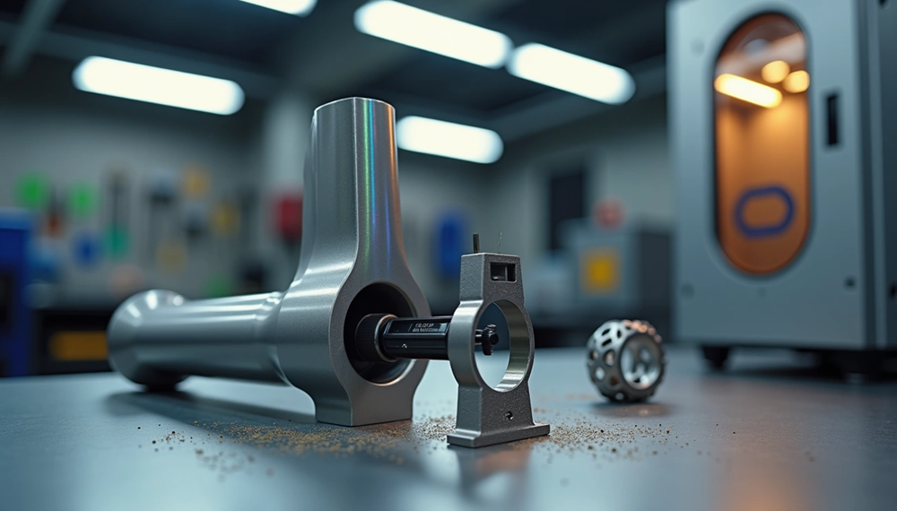
Titanium 3D printing typically achieves dimensional tolerances between ±0.1 mm to ±0.2 mm, which is nowhere near as precise as CNC machining’s ±0.005 mm capability. But engineers who combine 3d printing titanium with strategic design optimization can produce bicycle components that are up to 50% lighter than machined counterparts. This piece explores how manufacturers can maximize precision when working with titanium powder for 3d printing. Readers will find the most accurate 3d printing method for bicycle parts and critical factors affecting dimensional accuracy. They will also learn about post-processing techniques that bring 3D-printed titanium components within acceptable tolerances for high-performance cycling applications.
Understanding Dimensional Tolerances in Titanium 3D Printing
Standard Tolerance Ranges: ±0.1 mm to ±0.2 mm
Metal powder bed fusion processes achieve dimensional accuracy within specific ranges that depend on part geometry and size. Well-designed titanium 3d printed components can reach tolerances of ±0.076 mm plus ±0.0254 mm per mm of dimension. Most DMLS or SLM parts achieve ±0.2 mm accuracy in each axis, though suppliers quote ranges from ±0.1 to ±0.3 mm based on part dimensions.
Part size introduces a scaling factor that affects achievable precision. Larger systems with SLM technologies can maintain 25-50 micron accuracy for small components and 0.2% dimensional tolerance for larger parts. A 250 mm length component would have the correct specification of 250 mm ±0.5 mm. Entry-level systems achieve within 100 microns for smaller parts and 0.3% variation on larger dimensions.
The layer-by-layer build process determines resolution capabilities beyond overall dimensional accuracy. SLM systems feature 50-80 µm beam diameter in the XY plane and 20-40 µm layer height in the Z direction. Standard titanium 3d printing uses 0.06 mm layer thickness. Performance settings reduce this to 0.03 mm. Minimum wall thickness stands at 1 mm for standard applications and 0.5 mm for performance builds.
How Metal 3D Printing Tolerances Compare to CNC Machining
CNC machining delivers superior dimensional control when matched against additive manufacturing. 3d printing titanium achieves ±0.1 to 0.2 mm tolerances, while CNC operations maintain ±0.05 mm or better with capability down to 0.0002 inches from specified dimensions. Post-machining of 3D-printed parts can bring tolerances down to ±0.005 mm and combines design flexibility with precision.
Surface finish reveals another performance gap. CMM measurements on titanium parts show CNC achieving Ra 0.8 µm surface roughness versus metal AM’s Ra 5-10 µm in the as-printed state. Post-polishing brings additive parts to Ra 1.2 µm. The tolerance comparison positions metal 3D printing at ±0.01 to ±0.05 mm against CNC’s ±0.005 to ±0.02 mm range.
Powder bed metal printers operate between standard machining and fine machining tolerances. They are finer than plastic printing at ±0.2 to ±0.5 mm but looser than precision CNC work at ±0.01 mm. JHMIM Titanium houses three distinct production technologies under one roof and allows optimal process matching to each custom part requirement.
Critical Dimensions for Bicycle Frame Components
Dimensional variations in as-printed features require strategic planning for bicycle applications. A nominal 10 mm hole will measure 10.1 to 10.2 mm in the as-printed condition based on orientation and process parameters. Manufacturers address this by printing near-net-shape and machining critical features. Sanding or reaming is enough to achieve the required dimensions for less demanding interfaces.
Tighter tolerances increase production time and cost through slower printing speeds, finer layer settings, additional support structures, and expanded inspection protocols. The most accurate 3d printing method for bicycle components balances as-printed precision with post-processing efficiency and recognizes that critical surfaces like seatpost interfaces and headtube bores need secondary machining operations.
Factors That Affect Precision in 3D Printed Titanium Parts
Multiple interacting variables determine whether a titanium 3d printer can maintain dimensional accuracy throughout the build process. Understanding these factors allows engineers to predict and control deviation patterns in 3d printed titanium components.
Titanium Powder Quality and Particle Size Distribution
Particle characteristics affect layer consistency and final part accuracy. Titanium powder to use in 3d printing consists of spherical particles ranging from 15 to 150 microns in diameter, with precise size distribution controlled during manufacturing. Laser-based systems require 15-53μm fine powder due to tighter focusing spots. Electron beam systems accommodate 53-105μm coarse powder matched to their broader beam profiles.
Flowability determines powder bed uniformity and affects dimensional precision. Sphericity above 98% ensures smooth powder delivery during the recoating process. Particle size distribution affects packing density and sintering behavior. Narrow distributions reduce defects and improve layer adhesion. Chemical purity matters just as much. Oxygen content in titanium alloy powder must stay between 0.007% and 0.013% to prevent embrittlement and maintain mechanical properties.
Thermal Gradients and Cooling Rates During Printing
Solidification during laser-based 3d printing of titanium occurs under extreme thermal conditions that affect microstructure and dimensional stability. High solidification velocities combined with large thermal gradients characterize the fusion process. Cooling rates range from 2.12 × 10^4 K/s to 1.5 × 10^6 K/s and determine phase formation and residual stress accumulation.
Titanium’s high thermal conductivity enables rapid heat dissipation and creates thermal gradients across the part that cause residual stress. These stresses show as warping or distortion, especially in large components where temperature variations between recently printed top layers and cooled bottom sections become pronounced. The material undergoes solid-state phase transformations during cooling and adds complexity to thermal management requirements.
Build Orientation and Layer Height Selection
Part orientation relative to the build platform affects dimensional accuracy. Research demonstrates that upright orientation offers the highest accuracy by reducing layer shrinkage and enhancing precision with smaller contour sizes. Different angles produce measurable variations in surface quality and internal defects.
Surface roughness measures 43.68 μm when parts are built at 60° orientation and increases by 6% at 90°. Peak material volume varies from 0.002653 mm³/mm² at 60° to 0.003239 mm³/mm² at 90° orientations. Pore formation patterns shift with angle. The 90° orientations show a 32% decrease in pore count compared to other orientations.
Machine Calibration and Laser Parameters
Laser stability determines whether energy delivery remains consistent across the build. Calibrated systems maintain laser power standard deviation below 1% across different power levels. The 500W laser requires 14 seconds rise time to reach 95% of the nominal 285W power from startup.
Qualification protocols mandate calibration verification every 90 days to ensure laser focus, alignment and beam stability meet specifications. JHMIM Titanium houses three distinct production technologies under one roof and allows optimal process matching to each custom part while maintaining rigorous calibration standards across all systems. Beam positioning accuracy at the micron level translates to feature precision in the final component.
Selecting the Most Accurate 3D Printing Method for Bicycle Parts
Four main metal additive technologies compete for bicycle component production. Each offers distinct accuracy-performance trade-offs. Method selection determines whether parts meet dimensional requirements without excessive post-processing.
Selective Laser Melting (SLM) for Ti-6Al-4V Components
SLM produces melted titanium structures with superior machinability compared to wrought material. The fine, needle-like α′ martensite microstructure of SLM Ti-6Al-4V demonstrates resistance to deformation during secondary operations. Burr width reduction on the down-milling side reaches 71.6% at 1 μm/tooth feed rates compared to titanium processed through conventional methods.
Surface finish advantages position SLM as the most accurate 3d printing method for components that require minimal post-processing. Roughness after printing ranges from 5 μm to 10 μm, even after process optimization. Current technology produces thin walls and features at the 0.2 mm level. The rapid cooling inherent in SLM refines microstructures while forming martensitic α phase and improves mechanical strength and hardness by a lot.
Direct Metal Laser Sintering (DMLS) Precision Capabilities
DMLS achieves ±0.005 inch tolerance for the first inch, plus ±0.002 inch for every inch thereafter. Layer heights range from 0.0012 to 0.0016 inch depending on material selection. Parts reach 99% density by eliminating polymer binders and produce components with structural integrity that matches milled or formed parts.
Standard production tolerance stands at ±0.3% of feature size with a minimum of ±0.3 mm. Surface roughness after support removal measures 200-400 Ra. DMLS fuses metal powder together through selective laser sintering and this distinguishes it from full melting processes.
Electron Beam Melting (EBM) vs Laser-Based Processes
EBM delivers faster build speeds but sacrifices dimensional precision. Layer thickness measures 70 μm with a practical range of 50-200 μm. SLM achieves finer layers between 20 and 50 μm. The vacuum environment minimizes residual stresses and reduces warping risk for high-integrity aerospace applications.
SLM, comparatively, offers multiple laser capability up to 12 units and broader material compatibility. EBM beam positioning reaches 8000 mm/s scan speeds but produces coarser surface results that require post-processing for tight tolerances. The vacuum requirement limits build volume compared to SLM’s inert gas chambers.
Cold Metal Fusion (CMF) for Lower-Stress Printing
CMF bridges additive manufacturing flexibility with powder metallurgy reliability through a two-step process. Green parts printed below 80°C undergo debinding and sintering to achieve Ti-6Al-4V tensile strength up to 1,009 MPa. The method eliminates support structure requirements and reduces finishing costs by a lot compared to DMLS and SLM.
Production speed exceeds traditional metal additive manufacturing by three times while cutting per-part costs 50-60%. JHMIM Titanium houses three distinct production technologies under one roof and allows optimal process matching to each custom part requirement. This strategic approach ensures manufacturers select the appropriate method based on tolerance specifications, production volume and cost constraints specific to bicycle component applications.
Design Strategies to Achieve Tight Tolerances in Bicycle Components
Bicycle component geometry demands specific design accommodations to maintain dimensional stability during 3d printing titanium. Planning addresses material behavior, thermal stresses, and post-processing requirements before the first layer prints.
Wall Thickness Guidelines: 1mm to 1.75mm for Structural Parts
Bicycle frame lugs require wall thicknesses between 1mm and 1.75mm to balance structural integrity with weight constraints. Variations of just 0.25mm (0.010 inches) can render components unusable. Standard grade titanium maintains a 1mm minimum wall thickness, while performance applications work with 0.5mm walls. Optimal structural stability occurs at 2mm thickness. These parameters influence how titanium powder for 3d printing unites during fusion and subsequent cooling directly.
Internal Diameter Accuracy for Seatposts and Headtubes
Critical cylindrical features present the most demanding tolerance challenges. Internal diameters for seatpost clamps and headtube interfaces must maintain accuracy within 0.127mm (0.005 inches). Cylinders oriented parallel to the build plate develop stress profiles that vary around the circumference and result in oval cross-sections rather than true circles. Even well-laid-out builds produce undersized internal diameters by 0.508mm (0.020 inches), four times the acceptable variance. Then designers specify closed holes or offset dimensions during printing. This allows subsequent machining to achieve exact specifications without compromising structural integrity.
Support Structure Placement to Minimize Distortion
Topology optimization now extends beyond part geometry to support structure design and minimizes flatness errors while satisfying self-support criteria. Support placement reduces overall part distortion compared to regular column supports and targets planar features prone to warping. Parts require careful orientation planning to avoid support structures in inaccessible voids where removal becomes impossible. EDM-cut surfaces where supports attach show irregularities that require smoothing into the surrounding geometry.
Stress Relief and Hot Isostatic Pressing (HIP) Requirements
Build plates undergo stress relief at 600°C, held for three hours under argon atmosphere before cooling. HIP treatment follows at 900-950°C with pressures exceeding 1000 bar and eliminates internal porosity through plastic deformation, creep, and diffusion bonding. This process increases material density to match forged components while extending fatigue life by removing stress concentrators. Critical features requiring tight tolerances must be machined after heat treatment rather than before, as thermal processing causes dimensional movement. JHMIM Titanium houses three distinct production technologies under one roof and allows optimal process matching to each custom part while maintaining rigorous heat treatment protocols across all bicycle component applications.
Post-Processing Techniques for Precision Bicycle Components
Raw 3d printed titanium parts require sequential refinement to meet bicycle component specifications. Each post-processing stage addresses specific dimensional or material deficiencies inherent in additive manufacturing.
CNC Machining Critical Surfaces to ±0.005 mm
Precision machining brings critical interfaces to final dimensions after thermal processing. Advanced CNC equipment achieves tolerances down to ±0.005 mm on seatpost bores, headtube faces, and threaded features. Machining Ti-6Al-4V from 3d printing titanium generates cutting vibrations up to 5 kHz that accelerate tool wear. Stress-relief treatments beforehand reduce these vibrations to match traditionally manufactured material behavior.
Wire EDM Cutting and Support Removal Methods
Parts separate from build plates through wire EDM, which handles titanium’s low thermal conductivity without additional thermal stress. Support structures then require manual removal using wrenches, picks and mallets. Grinding operations on attachment points follow.
Heat Treatment to Reduce Built-in Stresses
As-built components contain residual stresses between 100-500 MPa. Stress relief occurs at 600°C for three hours under controlled atmosphere. Subsequent heat treatment raises yield strength to 950-1050 MPa. Hot Isostatic Pressing eliminates internal porosity and increases fatigue resistance up to one hundred times compared to untreated parts.
Surface Finishing: From Ra7 to Ra1.6
Metal 3D printing produces Ra7 surface roughness. Grinding operations refine this to 1.2-1.5 micrometers Sa. Final machining achieves Ra1.6 or better. JHMIM Titanium houses three distinct production technologies under one roof, allowing optimal process matching to each custom part throughout the complete post-processing workflow.
Conclusion
Titanium 3D printing delivers dimensional accuracies between ±0.1 mm to ±0.2 mm for bicycle components. Post-processing brings critical features to ±0.005 mm precision. Careful attention to powder quality and thermal management forms the basis of success. Build orientation and machine calibration matter too. To name just one example, SLM and DMLS provide the most accurate 3D printing approach for high-performance parts. Proper design strategies minimize distortion before machining refinements achieve final tolerances.
JHMIM Titanium stands as the only company in China housing three distinct production technologies under one roof. This setup allows optimal manufacturing process selection for each custom part and ensures exceptional precision and quality. The flexibility and expertise exist to meet demanding bicycle component specifications, whether manufacturers need small batches for bespoke projects or high-volume production capabilities.
FAQs
Q1. What dimensional tolerances can be achieved with 3D printed titanium bicycle components? Well-designed titanium 3D printed parts typically achieve tolerances of ±0.076 mm plus ±0.0254 mm per mm of dimension. Standard metal additive manufacturing processes produce parts with ±0.1 mm to ±0.2 mm accuracy, though tolerances may vary depending on part geometry and size. Post-processing techniques like CNC machining can refine critical surfaces to ±0.005 mm precision.
Q2. Which 3D printing technology offers the best accuracy for titanium bicycle parts? Selective Laser Melting (SLM) and Direct Metal Laser Sintering (DMLS) provide the highest accuracy for titanium bicycle components. SLM produces fully melted structures with as-printed surface roughness of 5-10 μm and can create features as small as 0.2 mm. DMLS achieves tolerances of ±0.005 inch for the first inch, making both methods ideal for precision bicycle applications.
Q3. How does powder quality affect the precision of 3D printed titanium parts? Titanium powder quality directly influences dimensional accuracy through particle size distribution and sphericity. Laser-based systems require fine powder (15-53 μm) for optimal precision, while sphericity above 98% ensures uniform powder bed layers. Chemical purity, particularly oxygen content between 0.007% and 0.013%, prevents defects that could compromise dimensional stability and mechanical properties.
Q4. What wall thickness is recommended for structural bicycle components in titanium 3D printing? Bicycle frame components require wall thicknesses between 1 mm and 1.75 mm to balance structural integrity with weight optimization. Standard grade applications maintain a 1 mm minimum wall thickness, while performance builds can work with 0.5 mm walls. Optimal structural stability occurs at 2 mm thickness, with variations as small as 0.25 mm potentially affecting component functionality.
Q5. What post-processing steps are necessary to achieve tight tolerances in 3D printed titanium bicycle parts? Post-processing involves multiple stages: stress relief heat treatment at 600°C for three hours, CNC machining of critical surfaces to ±0.005 mm, wire EDM for support removal, and surface finishing to reduce roughness from Ra7 to Ra1.6. Hot Isostatic Pressing (HIP) at 900-950°C eliminates internal porosity and increases fatigue resistance, with final machining performed after all heat treatments to maintain dimensional accuracy.