

Titanium can deliver exceptional strength-to-weight performance, but it punishes designs that ignore manufacturing reality. Unlike aluminum, titanium traps heat at the cutting edge, slows machining speeds, accelerates tool wear, and magnifies the cost of every unnecessary feature. For custom components, Design for Manufacturability is not just a review step—it is a cost-control strategy that affects billet size, tool life, machine time, and dimensional stability. This article explains how engineers can apply titanium-specific DFM principles to reduce the buy-to-fly ratio, choose better machining strategies, avoid distortion, and make design decisions that lower both tooling expense and unit cost before production begins.
Understanding DFM for Custom Titanium Parts
Design for Manufacturability (DFM) is a critical engineering discipline, but applying it to machined titanium requires a significant departure from conventional aluminum or steel guidelines. Because titanium alloys exhibit high strength-to-weight ratios alongside notoriously poor thermal conductivity, the material tends to trap heat at the cutting edge rather than dissipating it through the chip. For instance, milling Grade 5 titanium (Ti-6Al-4V) typically restricts cutting speeds to a narrow band of 30 to 45 meters per minute, compared to over 300 m/min for aluminum. This fundamental characteristic forces engineers to rethink part geometries to ensure economic viability in CNC machining and other subtractive processes. A central economic driver in this evaluation is the “buy-to-fly ratio”—the weight of the raw titanium billet compared to the weight of the finished component. High buy-to-fly ratios mean paying for expensive material only to spend costly machine hours cutting it away, making efficient design essential from the outset.
What DFM Means for Titanium Manufacturing
The core challenge of DFM for titanium is managing tool wear, galling, and thermal distortion through actionable design choices. Every complex feature, undercut, or non-standard angle directly multiplies the time the part must spend on the machine. To mitigate this, designers must clarify the distinction between two distinct manufacturing goals: minimizing total bulk material removal (near-net design) and maximizing the Material Removal Rate (MRR) during the machining operation.
Minimizing bulk removal reduces the amount of expensive titanium purchased and subsequently machined away. Conversely, maximizing MRR involves optimizing part rigidity and toolpaths so the machine can remove the necessary material as efficiently as possible without destroying tools. These goals are complementary, not contradictory. By simplifying geometries and aligning part orientations with standard multi-axis toolpaths, engineering teams can achieve both: less total material to cut, and a stable, efficient MRR for the material that must be removed.
Key Material and Geometry Constraints
Material properties also dictate strict geometric constraints, which vary significantly depending on the machining process. Titanium’s low modulus of elasticity makes it highly prone to chatter during CNC milling and springback during secondary forming operations. To prevent tool deflection in prismatic (milled) parts, designers should generally limit the depth of internal cavities to a maximum of 4:1 relative to the tool diameter.
However, it is crucial to distinguish between milling and turning constraints. Titanium is far more forgiving on a lathe than in a mill. Cylindrical parts should be explicitly flagged as candidates for lathe-first or Swiss-turn strategies rather than defaulting to multi-axis milling assumptions. Furthermore, because heat accumulation causes localized thermal expansion, designing parts with highly asymmetric mass distribution can lead to severe post-machining distortion. Symmetrical designs and the inclusion of stress-relief features are essential to maintaining dimensional stability throughout the manufacturing lifecycle.
DFM Choices That Reduce Cost and Risk
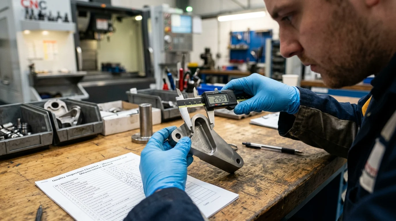
Implementing rigorous DFM principles early in the product development lifecycle directly correlates with reduced tooling expenditures and lower unit costs. Industry analyses consistently demonstrate that approximately 70% of a component’s final manufacturing cost is locked in during the design phase, making early optimization critical for commercial success.
Selecting the Right Manufacturing Process
The selection of the underlying manufacturing process dictates the applicable DFM rules and the resulting cost structure. While 5-axis CNC machining remains the standard for high-precision aerospace and medical components, alternative methods like Metal Injection Molding (MIM) or Direct Metal Laser Sintering (DMLS) offer distinct economic advantages for specific production volumes and geometries.
| Manufacturing Process | Optimal Volume (MOQ) | Typical Tooling Cost | Typical Economic Tolerance Band (mm) | Best Application |
|---|---|---|---|---|
| CNC Machining | 1 – 1,000 | Low to None | ± 0.050 to ± 0.100 | High precision, large parts, low volume |
| Metal Injection Molding (MIM) | 10,000+ | High ($10k – $30k) | ± 0.3% of dimension | Small, highly complex parts, mass production |
| Additive Manufacturing (DMLS) | 1 – 500 | None | ± 0.100 to ± 0.200 | Complex internal channels, lightweight lattices |
Matching the design to the process prevents costly over-engineering, but niche processes come with critical mechanical-property caveats. While MIM and DMLS can drastically reduce unit costs or enable complex geometries, parts produced via these methods typically exhibit lower fatigue life and reduced ductility compared to wrought CNC-machined titanium. Aerospace and medical designers must not select a process based solely on tooling or unit-cost comparisons without validating these mechanical trade-offs. Additionally, titanium MIM requires highly controlled debinding environments to avoid carbon or oxygen contamination, and DMLS parts require support structure removal and stress-relief heat treatments.
Optimizing Wall Thickness, Radii, Holes, and Finish
When CNC machining is the chosen route, specific feature optimizations yield immediate cost reductions. Wall thicknesses should generally be maintained above 1.5 mm; thinner walls vibrate excessively during machining, requiring specialized workholding or slower feed rates that inflate cycle times. Internal corner radii must also accommodate standard end mills. Specifying an internal corner radius slightly larger than the tool’s own radius—such as a 3.5 mm radius for a 6.0 mm diameter tool—allows smooth, continuous motion through the corner, thereby reducing stress concentrations and tool chatter.
Hole design requires careful attention. Blind tapped holes in titanium are a major cost and risk driver due to the material’s tendency to gall and break taps. Whenever possible, designers should specify through-holes rather than blind holes to allow better chip evacuation and coolant flow. When internal threads are required, thread milling is highly preferred over traditional tapping, as it exerts less cutting pressure and allows for easier tool extraction if breakage occurs. If blind tapped holes are unavoidable, limit thread depth to 1.5x to 2x the nominal hole diameter. Finally, specify a standard machined finish (Ra 1.6 to 3.2 µm) to control costs, as polishing titanium is highly labor-intensive.
Applying DFM in Engineering and Procurement
Bridging the gap between theoretical CAD models and the reality of the shop floor requires integrating
Key Takeaways
- Design titanium parts around low cutting speeds, since Grade 5 titanium is typically machined at about 30 to 45 m/min versus over 300 m/min for aluminum.
- Reduce the buy-to-fly ratio early by using near-net shapes and avoiding designs that require excessive titanium billet removal.
- Keep milled internal cavities within an approximate 4:1 depth-to-tool-diameter ratio to limit tool deflection, chatter, and tool wear.
- Flag cylindrical titanium components for lathe-first or Swiss-turn review before assuming a multi-axis milling process.
- Use symmetrical mass distribution and stress-relief features to reduce thermal distortion and improve dimensional stability after machining.
- Simplify non-standard angles, undercuts, and hard-to-reach features because each added complexity increases setup time, tooling demand, and unit cost.
Frequently Asked Questions
Why does titanium require different DFM rules than aluminum or steel?
Titanium has low thermal conductivity, so heat stays near the cutting edge and accelerates tool wear. This limits cutting speeds and makes geometry, tool access, rigidity, and material removal strategy much more important than with easier-to-machine metals.
What is the buy-to-fly ratio in titanium machining?
The buy-to-fly ratio compares the starting billet weight to the final part weight. A high ratio means expensive titanium is purchased and then machined away, increasing both material cost and machine time.
How can DFM reduce tooling costs for custom titanium parts?
DFM reduces tooling cost by simplifying features, avoiding deep cavities, improving tool access, reducing chatter, and allowing stable cutting parameters. These choices help prevent premature tool wear and repeated setup changes.
What cavity depth is generally recommended for milled titanium parts?
For CNC-milled titanium parts, internal cavity depth should generally stay within a 4:1 depth-to-tool-diameter ratio. Deeper cavities increase deflection, chatter, tool wear, and machining time.
When should a titanium part be considered for turning instead of milling?
Cylindrical or rotationally symmetric titanium parts should be reviewed for lathe-first or Swiss-turn manufacturing. Turning is often more efficient and stable for round geometries than defaulting to multi-axis milling.