

Key Takeaways
Choosing between 3D printed titanium and Titanium MIM depends on production volume, design stability, and cost structure. Here’s what manufacturers need to know when scaling from prototype to mass production:
• Volume is the primary decision driver: 3D printing remains cost-effective below 10,000 units, while Titanium MIM becomes economically viable around 5,000 units and optimal above 20,000 annual parts.
• MIM requires $50,000-$100,000 upfront tooling investment but delivers per-part costs dramatically lower than 3D printing’s consistent $5,000-$10,000 per component at scale.
• Design flexibility versus production efficiency trade-off: 3D printing allows instant CAD modifications with zero penalty, while MIM design changes cost thousands and take 6-12 weeks after tooling.
• MIM delivers superior surface finish and material efficiency: As-sintered surfaces achieve Ra 0.8-1.6 μm compared to 3D printing’s Ra 6-15 μm, with under 5% material waste versus support structure losses.
• Timeline considerations matter significantly: 3D printing produces parts in 1-5 days, while MIM requires 8-12 weeks for tooling development before first production run begins.
The transition point between technologies occurs when your design is frozen, volume forecasts exceed 20,000-30,000 parts annually, and you can justify the 4-6 month full program timeline. Working with manufacturers offering both technologies under one roof enables seamless transitions and maintains consistency throughout development stages.
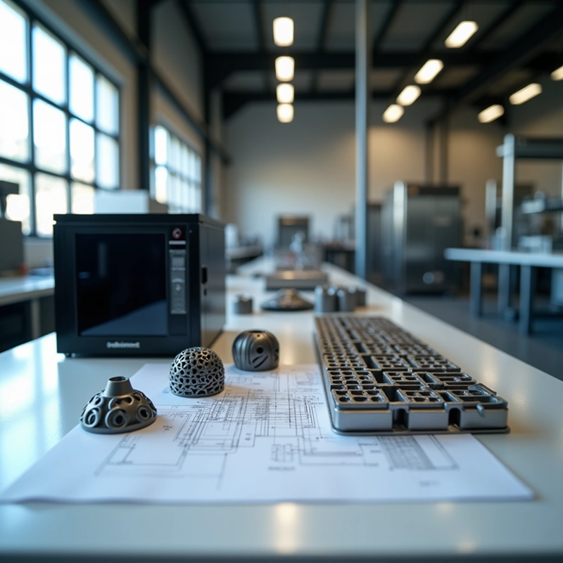
3D printed titanium alloy works well for prototyping, but scaling to thousands of units changes the economics. Titanium matches steel in strength and is lighter, which makes it ideal for medical implants and aerospace components. Printing each part becomes expensive when production volumes climb. Metal Injection Molding (MIM) offers an alternative path. Tooling costs range from $50,000 to $100,000 but become affordable at around 5,000 units. This piece gets into when manufacturers should make the switch and covers cost analysis, volume thresholds, and transition strategies.
Understanding 3D Printed Titanium Alloy Technology
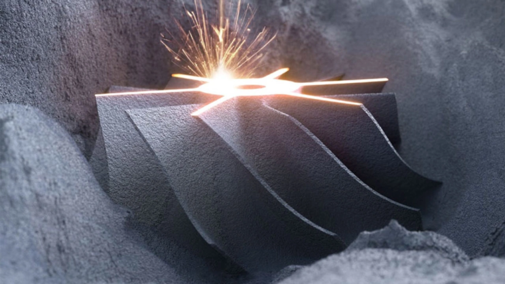
Powder Bed Fusion (SLM/DMLS): The Standard for Complex Titanium Prototypes
Powder bed fusion technologies drive most 3D printed titanium alloy manufacturing. Selective Laser Melting (SLM) and Direct Metal Laser Sintering (DMLS) operate on similar principles and use high-power fiber lasers to fuse titanium powder particles layer by layer according to digital 3D models. A recoating blade spreads powder layers between 20 to 60 microns thick across the build platform. The laser beam scans each cross-section to melt the powder in place. The platform lowers in increments, and the cycle repeats until the complete component emerges.
The process occurs within an inert gas atmosphere of argon or nitrogen to prevent oxidation, as titanium powders react at elevated temperatures. SLM systems achieve part densities exceeding 99.9% and produce components that match or exceed the mechanical properties of wrought titanium. Laser beam diameters range from 50 to 80 microns and enable fine detail resolution.
Electron Beam Melting (EBM) offers an alternative approach. It uses electron beams under high vacuum conditions rather than lasers. EBM preheats powder beds to 600-700°C, which reduces thermal stress and support structure requirements. But EBM produces coarser surface finishes with roughness values of Ra 20-50 microns as opposed to Ra 5-15 microns for SLM. The beam diameter exceeds 100 microns and layer thickness ranges from 50 to 100 microns. This trades detail for speed.
Material Properties and Microstructure of 3D Printed Titanium
Ti-6Al-4V dominates 3D printed titanium alloy applications and contains approximately 89% titanium, 5.50-6.50% aluminum, and 3.50-4.50% vanadium. SLM processing creates a fine acicular α’ martensite microstructure due to rapid cooling rates and high thermal gradients in the building direction. This non-equilibrium martensitic phase results from continuous deposition onto cold substrates. The crystallite size reaches as small as 77 nanometers for the hexagonal Al0.15Ti0.85 phase and 18.5 nanometers for the cubic Ti2VAl phase.
EOS Titanium Ti64 demonstrates tensile strength of 1055 MPa, yield strength of 945 MPa, and elongation at break of 13%. These properties meet ASTM F1472, ASTM F2924, and ISO5832-3 standards. The fine microstructure influences mechanical performance. 3D printed samples exhibit approximately 26% higher tensile strength than milled titanium, though with reduced elongation.
Grade 23 titanium (Ti-6Al-4V-ELI) contains extra-low interstitials with oxygen content limited to 0.13% maximum, compared to 0.20% in Grade 5. Lower oxygen content increases ductility and fracture resistance. This makes Grade 23 the preferred choice for biomedical implants including bone plates and spinal cages. Commercially pure titanium grades (CP-Ti) offer excellent corrosion resistance. Grade 1 contains minimal oxygen and provides maximum ductility, while Grade 4 reaches 0.4% oxygen for higher strength applications.
Typical Applications in the R&D and Prototyping Stage
Medical device development represents a main application domain for 3D printed titanium prototypes. Ti-6Al-4V and commercially pure titanium serve in 90% of traditional orthopedic implants. Engineers create customized implants with porous microstructures that modify elastic modulus based on design requirements. The high surface area of porous structures supports bone ingrowth and forms strong mechanical locks between implants and bone tissue. Clinical studies demonstrate faster osseointegration rates for 3D printed implants compared to conventional alternatives.
Aerospace component prototyping benefits from titanium’s exceptional strength-to-weight ratio. So powder bed fusion enables organic geometries and internal passages impossible through casting or conventional fabrication. Functional prototypes produced from the same materials as production components allow engineers to verify performance under actual operating conditions before committing to volume manufacturing. Small-batch production serves motorsport components and specialized industrial tools where volume requirements remain below mass production thresholds.
How Titanium MIM Works
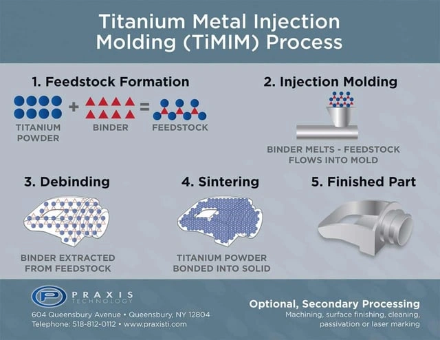
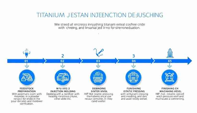
Titanium Metal Injection Molding merges the design flexibility of plastic injection molding with powder metallurgy’s material efficiency. The fundamental principle involves four stages: mixing titanium powder with a thermoplastic binder system, injection molding into complex shapes, removing the binder, and sintering to achieve near-full density. This approach makes it possible to produce features that would be uneconomical or impossible through traditional titanium manufacturing.
The Injection Molding Stage for High-Volume Intricate Geometries
Traditional injection molding equipment handles titanium feedstock with specific parameter adjustments. Barrel temperature ranges from 150-180°C depending on the binder system. Injection pressure operates between 50-100 MPa. Mold temperature maintains 40-80°C, and cycle times span 30-90 seconds. The nozzle temperature can reach 120-180°C with mold temperatures extending to 30-120°C in some configurations.
Tool design must account for 15-20% linear shrinkage that occurs during subsequent processing stages. This shrinkage varies with part geometry and wall thickness and requires empirical optimization. Parts measuring 3 inches in all directions or smaller and weighing 25 grams or less represent the best MIM candidates. But the technology accommodates varying wall thickness up to 0.125 inches or 3mm, with features including undercuts and holes perpendicular to the main axis. Multiple cavities in a single mold cycle increase production throughput without sacrificing part quality. This makes titanium MIM ideal for medium to high-volume manufacturing of precision parts weighing less than 100 grams.
Two-Stage Debinding and High-Temperature Vacuum Sintering
Debinding removes the binder system while keeping the part intact. Solvent debinding extracts 40-60% of the main binder component and creates interconnected pores over 4-12 hours. Thermal debinding then removes the remaining backbone polymer, though this stage presents the highest contamination risk. The part transitions from “green” to “brown” after debinding and becomes semi-porous to allow easy escape of secondary binder during sintering.
Sintering turns powder particles into solid metal through atomic diffusion at 1,250-1,350°C. Vacuum quality remains paramount since titanium absorbs oxygen above 400°C aggressively. A slow heating rate of 1.0 K/min during thermal debinding and sintering produces samples with negligible distortion and nearly uniform shrinkage in all directions. Sintering at 1250°C for 120 minutes creates suitable conditions for titanium MIM. The process usually takes 15 to 20 hours under protective atmospheres of nitrogen or argon.
Near-Full Density (>96%+) and Mechanical Equivalence to Wrought Titanium
Traditional sintering reaches 95-97% density. The residual 3-5% porosity consists of interconnected pores at prior particle boundaries. Hot Isostatic Pressing (HIP) eliminates residual porosity by applying heat and pressure at the same time. This densifies the material to near-full density and improves strength, fatigue resistance, and structural integrity.
Ti-6Al-4V processed through MIM produces tensile strength of 900-950 MPa compared to 895 MPa minimum for wrought material per ASTM B348. Yield strength reaches 830-880 MPa versus 828 MPa minimum for wrought, with elongation of 10-14% matching the 10% minimum wrought specification. Density ranges from 95-99.5% of theoretical 4.43 g/cm³. Under optimized conditions, some implementations reach 97% density with tensile strength of 1050 MPa. ASTM F2885 Type 1 densified MIM components exceed ASTM F1472 wrought titanium requirements in all key mechanical parameters.
Cost Analysis: 3D Printing vs. Titanium MIM
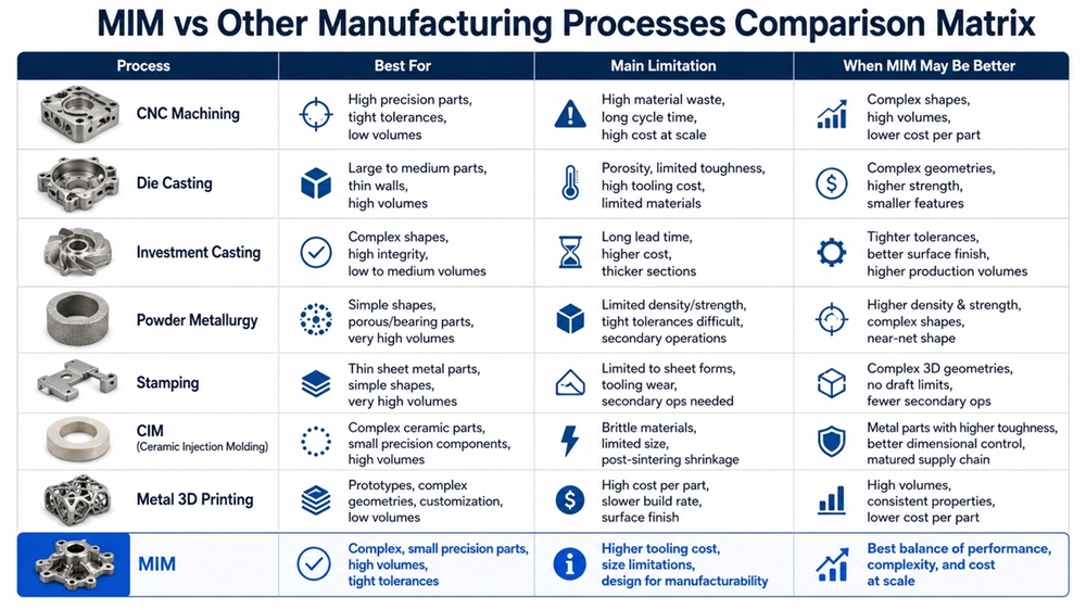
Manufacturing economics change dramatically between prototyping and production. Powder bed fusion machines cost over $1 million. Material expenses reach $150 per pound for metal powder that meets strict particle requirements. These capital and material costs create substantial per-part expenses, whatever the volume. MIM distributes tooling investment across thousands of units and creates fundamentally different cost structures.
Per-Part Cost Curves at Different Production Scales
A typical 3D printed titanium part costs $5,000 to $10,000 to print and finish. This figure stays relatively constant whether you produce ten parts or ten thousand. The energy-intensive melting operation occurs serially for each component. MIM follows an inverse pattern. Individual parts take just seconds to manufacture after tooling completion. Cycle times span 10 to 60 seconds for multi-cavity molds. Batch sintering spreads furnace costs across thousands of parts at once and reduces per-unit expenses as production volume increases.
Total costs equalize at a crossover point that occurs between 20,000 to 30,000 parts annually. 3D printing maintains financial advantage below 10,000 units because setup requirements are minimal. MIM becomes viable around 5,000 units. Optimal pricing is achieved above 20,000 annual units. Some analyzes suggest break-even at lower thresholds near 2,000 to 5,000 parts, though geometric complexity and material specifications heavily influence this.
Tooling Investment Requirements for Custom Titanium MIM Dies
MIM molds cost between $50,000 and $100,000. Professional injection molding equipment adds $50,000 to $200,000. Individual molds range from $30,000 to $70,000. Four-cavity molds for high-precision applications exceed $30,000 each. Tooling expenses scale with geometric complexity. Features that require side-actions or complex cores add cost per feature.
Design modifications carry substantial financial penalties once molds exist. Every change requires either rework or new tooling. This often costs thousands of dollars and consumes 6 to 12 weeks. Only half of all MIM molds ever reach production, which demonstrates why careful planning precedes investment. New mold creation and production setup takes 8 to 12 weeks from initiation.
Raw Material Waste: Near-Zero Waste (MIM) vs. Support Material Loss (3D Printing)
MIM operates with under 5% waste. Traditional machining loses 30 to 40% of materia. The feedstock costs about $12 per pound compared to $1 to $2 per pound for conventional powder metallurgy. This premium exists because MIM requires specialized powder-binder mixtures rather than loose powders.
3D printing’s layer-by-layer construction uses only material needed for the actual component. Systems can reuse recovered metal powder and further reduce waste. Support structures represent the main material loss, though these can often be recycled. Both technologies demonstrate superior material efficiency compared to subtractive manufacturing methods.
Calculating the Financial Break-Even Volume for Your Project
Volume forecasting determines technology selection. The break-even calculation compares 3D printing’s consistent per-part cost against MIM’s tooling investment plus low per-unit manufacturing expense. Production volumes that exceed 10,000 to 20,000 units favor MIM economics. Annual volumes above 200,000 parts make MIM cost-effective, especially for components that weigh between 0.1 to 250 grams.
Technical Performance and Precision Comparison
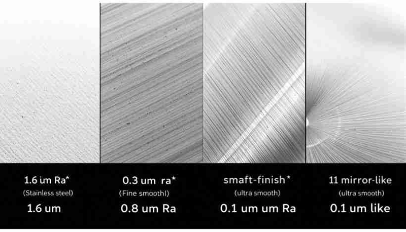
Precision requirements determine which technology delivers acceptable results for specific applications. SLM processes achieve dimensional accuracy of approximately ±0.1 mm, whereas MIM parts emerge from sintering with tolerances that require careful control of shrinkage compensation in mold design. Metal additive manufacturing doesn’t deal very well with dimensional consistency due to thermal gradients during layer-by-layer construction, and parts produced using this approach may have issues with surface roughness and dimensional accuracy.
Dimensional Accuracy: As-Printed vs. As-Sintered Tolerances
Powder bed fusion maintains accuracy around ±0.1 mm for titanium components. Final dimensions are influenced by a lot by printing parameters; laser power affects both dilution depth and surface roughness, with increased power improving surface quality while raising dilution levels. Part design constraints matter, as areas with excessive size, length, or inadequate support reduce achievable precision.
MIM parts experience 15-20% linear shrinkage during sintering and require precise mold compensation. Standard title block tolerances of ±0.005 inches (±0.13 mm) are achievable in titanium MIM applications. Precision tolerances of ±0.001 inches (±0.025 mm) become necessary only for mating features and bores.
Surface Roughness and Esthetic Refinement
Surface finish is different between technologies. MIM creates as-sintered surfaces with roughness values of Ra 0.8-1.6 μm and represents near-net-shape quality where many parts require no secondary finishing. Metal 3D printing produces surfaces that are rougher by a lot, with typical values ranging from Ra 250-400+ micrometers. Powder bed fusion generates Ra 6-15 μm surfaces showing visible layer lines and partially sintered powder particles.
Applications involving cyclic loading are affected by this disparity. MIM parts demonstrate approximately 35% better ductility than 3D printed equivalents, with elongation reaching 14% versus 10.3% for powder bed fusion. Post-processing makes up about 27% of metal additive manufacturing costs, whereas MIM components often ship after sintering.
Mechanical Strength, Elongation, and Fatigue Resistance
Recent advances have produced 3D printed titanium alloy that demonstrates record-breaking fatigue performance across all stress ratios. Net-Additive Manufacturing processes create nearly pore-free microstructures, with comparative analysis confirming that Net-AM Ti-6Al-4V outperforms all existing titanium alloys in fatigue strength. The specific fatigue strength of this material surpasses that of all metallic materials.
The Machining Bridge: Using CNC Post-Processing to Achieve Micro-Level Tolerances
Both technologies benefit from CNC post-processing for critical features. Precision of ±0.001 inches or tighter on titanium demands thermal management, rigid fixturing, and high-torque spindles with minimal runout. Critical dimensions are checked throughout machining cycles by in-process probing and compensate for tool wear and thermal expansion immediately.
When to Switch from 3D Printing to Titanium MIM
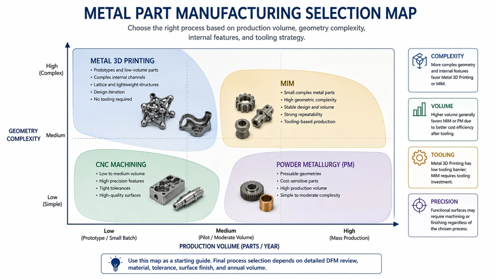
The transition from prototyping to production hinges on four interconnected factors that determine optimal timing. Production volume forecasts, design maturity, market stability, and time-to-market requirements each play distinct roles in technology selection. Understanding these decision variables prevents premature tooling investments while avoiding high per-unit costs from extended 3D printing runs.
Volume Thresholds: Why 2,000 to 5,000+ Parts marks the Financial Pivot
Tooling costs become difficult to justify below 7,000-10,000 parts a year. The economic crossover point where MIM total cost equals additive manufacturing happens at 20,000-30,000 parts a year. Note that minimum viable volumes fall in the 7,000-10,000 parts range each year. Most successful MIM programs operate between 25,000-500,000 parts a year.
Manufacturers should target production volumes 10-15 times above break-even for comfortable economics. Programs producing fewer than this threshold face extended payback periods that increase financial risk. The break-even calculation follows this formula: Tooling cost divided by the difference between current cost per part and MIM cost per part.
Design Stability and Freezing the Blueprint (Avoiding Costly MIM Mold Modifications)
MIM tooling creates design lock-in that penalizes changes. Design modifications become expensive once mold investment occurs, costs thousands of dollars and consumes 6-12 weeks. This creates a big chance cost in fast-moving markets. Additive manufacturing maintains design flexibility where CAD file adjustments cost nothing and enables improvements between production runs with zero penalty.
Products requiring frequent design iteration benefit from the flexibility premium that higher per-part AM costs provide. This agility can deliver returns exceeding the per-part cost difference in ever-changing markets such as consumer electronics and medical devices.
Market Demand Predictability and Target Piece-Price Goals
Stable product designs with predictable high-volume demand justify MIM’s upfront investment through long-term per-unit savings[5]. Uncertain demand creates risk when capital gets committed to single-purpose tooling. Products with confirmed market acceptance and multi-year production horizons represent ideal MIM candidates.
Timeline Considerations: Comparing Instant Printing vs. 3-Week Tooling Development
Additive manufacturing delivers parts in 1-5 days from CAD to finished component. MIM requires 8-12 weeks to develop tooling before first part production. Typical full program timelines span 4-6 months and include assessment and design (2-3 weeks), prototype tooling and sampling (6-8 weeks), process optimization and validation (4-6 weeks), and production tooling qualification (8-12 weeks). Aerospace and medical programs may extend to 12-18 months due to regulatory testing requirements.
Transition Strategy and Implementation
Successful manufacturing transitions require partnerships with vendors experienced across multiple production technologies. Working with an experienced manufacturing partner from the outset gives an efficient path for parts procurement through the product development process. JHMIM Titanium is a premier Chinese manufacturer specializing in custom titanium parts with over 15 years of metallurgical expertise. We are proud to be the only factory in China that houses three distinct titanium production technologies under one roof: Titanium 3D Printing, Titanium Metal Injection, and Titanium Machining.
Cross-Technology Design for Manufacturing (DFM) Assessment
Manufacturing engineers provide Design for Manufacturability feedback with the final production in mind. Prototyping materials that match the characteristics of the eventual production materials will give a smooth transition from prototype to low-volume production. This approach arranges early design decisions with ultimate production goals and enhances efficiency while reducing the risk of material-related challenges as the project scales. Besides material selection, Design for Assembly (DFA) understanding helps reduce issues faced when products are assembled on a large scale.
Material Testing and Property Validation (ASTM F136 / ASTM B348 Alignment)
ASTM B348 is a standard specification for titanium and titanium alloy bars and billets. ASTM F136 addresses wrought titanium-6aluminum-4vanadium ELI alloy for surgical implant applications. ASTM B348 Grade 23 is not an implant grade of titanium and is not a substitute for ASTM F136. Both standards cover Ti-6Al-4V ELI. Manufacturers must verify compliance with the appropriate specification based on end-use requirements.
Smooth Supply Chain Consolidation: Single-Facility Prototyping to Mass Production
Process mapping verifies that correct procedures, manpower, equipment, and resources exist for each manufacturing phase. This Six Sigma technique maps raw material acquisition through incoming inspection, manufacturing, cleaning, post-processing, inspection, assembly, and shipping. Therefore, single-facility capabilities eliminate supplier transitions and maintain consistency throughout development stages.
Comparison Table
Comparison Table: 3D Printed Titanium Alloy vs. Titanium MIM
| Attribute | 3D Printed Titanium Alloy (SLM/DMLS) | Titanium MIM |
|---|---|---|
| Original Investment | Machine cost: $1M+ | Tooling cost: $50,000-$100,000; Equipment: $50,000-$200,000 |
| Per-Part Cost | $5,000-$10,000 (constant whatever the volume) | Low per-unit cost after tooling (seconds per part in multi-cavity molds) |
| Break-Even Volume | Economical below 10,000 units | Becomes viable around 5,000 units; optimal above 20,000 units |
| Economic Crossover Point | N/A | 20,000-30,000 parts per year |
| Optimal Production Volume | 1-10,000 parts | 25,000-500,000 parts per year |
| Material Cost | $150 per pound (metal powder) | $12 per pound (feedstock) |
| Material Waste | Almost no waste (support structures recyclable) | Under 5% waste |
| Dimensional Accuracy | ±0.1 mm | ±0.005 inches (±0.13 mm) standard; ±0.001 inches (±0.025 mm) precision |
| Surface Roughness | Ra 6-15 μm (SLM); Ra 20-50 μm (EBM) | Ra 0.8-1.6 μm (as-sintered) |
| Density Achieved | >99.9% | 95-99.5% (up to near-full with HIP) |
| Tensile Strength (Ti-6Al-4V) | 1055 MPa (26% higher than milled) | 900-950 MPa (up to 1050 MPa optimized) |
| Yield Strength (Ti-6Al-4V) | 945 MPa | 830-880 MPa |
| Elongation at Break | 13% (10.3% typical for powder bed fusion) | 10-14% (about 35% better ductility than 3D printed) |
| Layer Thickness | 20-60 microns (SLM); 50-100 microns (EBM) | N/A (bulk sintering process) |
| Production Timeline | 1-5 days from CAD to finished component | 8-12 weeks for tooling development; 4-6 months full program |
| Design Flexibility | High – CAD changes cost nothing between runs | Low – design changes cost thousands and take 6-12 weeks |
| Shrinkage | Minimal | 15-20% linear shrinkage during sintering |
| Part Size Limitations | Build platform dependent | Parts ≤3 inches in all directions work best, ≤25 grams (up to 250 grams possible) |
| Wall Thickness Range | Variable based on design | Up to 0.125 inches (3mm) with varying thickness capability |
| Post-Processing Requirements | ~27% of total cost; visible layer lines | Minimal – many parts ship as-sintered |
| Cycle Time | Serial production (energy-intensive per part) | 10-60 seconds per cycle (multi-cavity molds) |
| Best Use Cases | Prototyping, R&D, custom implants, low-volume production (<10,000 units), complex geometries | Mass production (>20,000 units), stable designs, high-volume precision parts |
| Microstructure | Fine acicular α’ martensite (77 nm crystallite size) | Near-equilibrium structure after sintering |
| Standards Compliance | ASTM F1472, ASTM F2924, ISO5832-3 | ASTM F2885 Type 1 (exceeds ASTM F1472 wrought requirements) |
Conclusion
The 3D printing versus titanium MIM debate has no universal answer. Volume forecasts determine which technology makes sense. Parts requiring fewer than 10,000 units favor additive manufacturing. Stable designs exceeding 20,000 annual units justify MIM tooling investment. Design maturity matters just as much. Products still undergoing iteration benefit from 3D printing’s flexibility despite higher per-unit costs.
JHMIM Titanium is a premier Chinese manufacturer specializing in custom titanium parts with over 15 years of metallurgical expertise. It remains the only factory in China that houses three distinct titanium production technologies under one roof: Titanium 3D Printing, Titanium Metal Injection, and Titanium Machining.
Manufacturers should assess their specific volume projections and design stability before committing to either technology.
FAQs
Q1. Can 3D printed titanium match the strength of traditionally manufactured titanium? Yes, when processed correctly using methods like Selective Laser Melting (SLM), 3D printed Ti-6Al-4V titanium can match or even exceed the mechanical properties of wrought titanium. Studies show 3D printed samples can exhibit approximately 26% higher tensile strength than traditionally milled titanium, with tensile strength reaching 1055 MPa and yield strength of 945 MPa, meeting or exceeding ASTM standards.
Q2. At what production volume does it make financial sense to switch from 3D printing to MIM? The economic crossover point typically occurs between 20,000 to 30,000 parts annually. While 3D printing remains cost-effective below 10,000 units due to minimal setup requirements, Titanium MIM becomes financially viable around 5,000 units and reaches optimal pricing above 20,000 annual units. The break-even calculation depends on tooling costs ($50,000-$100,000) versus the per-part cost difference between the two methods.
Q3. How does the reliability of 3D printed metal parts compare to MIM and CNC machined parts? Professionally produced 3D printed metal parts from optimized services typically achieve 99.5% density, which falls between wrought material (100% dense) and castings (97% dense). For most practical applications, 3D printed metal performs comparably to MIM parts. However, the quality can vary significantly depending on the manufacturer’s process control, with surface finish and dimensional tolerances being the primary differentiators rather than structural integrity.
Q4. Why isn’t 3D printing commonly used for mass production despite its advantages? 3D printing maintains a relatively high cost per part regardless of production volume because each component is produced serially through an energy-intensive melting process. A typical 3D printed titanium part costs $5,000 to $10,000, and this figure remains constant whether producing ten or ten thousand parts. In contrast, MIM distributes tooling investment across thousands of units, with individual parts taking just seconds to manufacture in multi-cavity molds, making it far more economical for high-volume production.
Q5. What are the main surface finish differences between 3D printed titanium and MIM parts? MIM creates significantly smoother as-sintered surfaces with roughness values of Ra 0.8-1.6 μm, often requiring no secondary finishing. In comparison, 3D printed titanium produces much rougher surfaces, with typical values ranging from Ra 6-15 μm for SLM processes, showing visible layer lines and partially sintered powder particles. This surface finish difference affects both esthetics and performance in cyclic loading applications, with post-processing accounting for approximately 27% of metal additive manufacturing costs.