

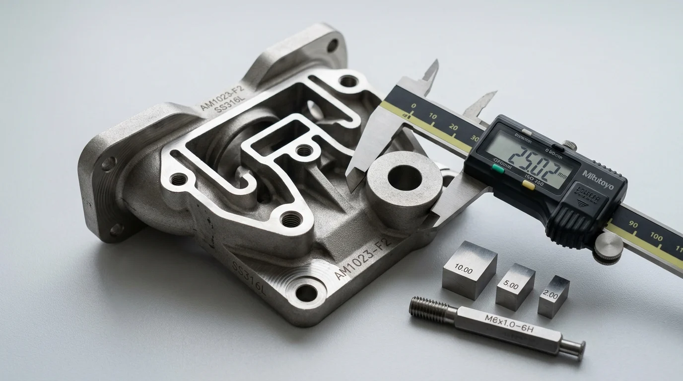
Dimensional control in metal additive manufacturing is not just a quality issue—it determines whether a printed component fits, functions, and stays cost-effective. Unlike machining, where rigid tools define geometry, metal AM depends on powder behavior, laser parameters, thermal contraction, support strategy, and post-processing. That means a tolerance that looks routine on a drawing may be unrealistic or expensive on an as-printed titanium or metal alloy part. This guide explains practical tolerance ranges, the difference between accuracy and repeatability, why warping happens, and how engineers should specify critical features before production begins.
Why Metal 3D Printing Tolerances Matter
Metal additive manufacturing (AM) has shifted from a rapid prototyping tool to a robust production method for end-use components. However, transitioning a design from digital geometry to physical metal requires a rigorous understanding of metal 3D printing tolerances. Unlike traditional subtractive manufacturing, where precision is dictated by rigid cutting tools and fixture setups, metal AM relies on thermal processes that introduce unique metallurgical and dimensional variations.
Impact on Fit, Function, and Cost
The relationship between specified tolerances and final part cost is highly non-linear in metal additive manufacturing. Demanding a tolerance of ±0.05 mm on an as-printed surface is often physically impossible without secondary operations. When engineers over-specify tolerances, manufacturers must implement CNC machining, specialized fixturing, and advanced heat treatments. This transition from a standard as-printed tolerance of ±0.5 mm to a precision-machined tolerance of ±0.05 mm can easily increase the final unit cost several-fold. Consequently, understanding which features strictly require tight tolerances is essential for maintaining the economic viability of the AM process.
Common Tolerance Risks for Commercial Parts
Commercial metal parts face specific tolerance risks primarily driven by thermal dynamics. Rapid heating and cooling cycles create severe residual stresses within the build volume. If these stresses are not managed through proper support structures and orientation, they lead to thermal distortion, warping, or even catastrophic build failure. For instance, unsupported overhangs or massive cross-sections can experience warping that deviates from nominal dimensions by several millimeters. In unoptimized production runs, failing to account for these thermal distortions can result in significant scrap rates. Mitigating these risks requires predicting thermal behavior and compensating for shrinkage before the laser touches the powder bed.
How to Define Tolerances Before Design
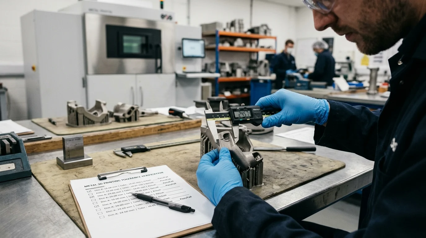
Establishing realistic tolerances begins long before the CAD file is exported for printing. Engineers must adopt an additive mindset, abandoning the default title block tolerances that govern conventional CNC machining. Defining tolerances for metal AM requires a strategic approach that distinguishes between the capabilities of the printing hardware and the realities of the material being processed.
Dimensional Accuracy vs. Repeatability
A common point of confusion in metal AM is the distinction between dimensional accuracy and process repeatability. Dimensional accuracy refers to how closely the printed part matches the nominal CAD geometry. For most laser powder bed fusion (LPBF) systems, as-printed accuracy typically ranges from ±0.1 mm to ±0.2 mm for small to medium features. Repeatability, however, measures the variation across multiple parts within the same build or across consecutive builds. Modern industrial AM systems can achieve consistent repeatability, often demonstrating stable standard deviations across a fully populated build plate. This reliability allows manufacturers to apply consistent scaling factors to the CAD model, systematically compensating for predictable shrinkage and improving overall accuracy over successive iterations.
Appropriate Drawing Notes and GD&T Controls
Traditional linear tolerancing is frequently inadequate for the complex, organic geometries characteristic of metal 3D printing. Instead, engineers must rely heavily on Geometric Dimensioning and Tolerancing (GD&T) standards, such as ASME Y14.5 or ISO 1101. For as-printed organic surfaces, applying a Profile of a Surface tolerance—typically ranging from 0.2 mm to 0.5 mm—is far more effective than assigning strict linear limits. This provides the manufacturer with an acceptable envelope for the entire surface, accommodating the natural layer-stepping and thermal variations inherent to the process. Critical interfaces should be explicitly marked for secondary operations, with corresponding datum structures established on stable, as-printed surfaces.
Tolerance Differences by Process and Material
Metal 3D printing is not a monolith; it encompasses several distinct technologies, each interacting with raw materials differently. The choice of process, material, and spatial orientation directly dictates the achievable tolerances.
Typical Tolerances for Metal AM Processes
Major metal AM processes—such as Direct Metal Laser Sintering (DMLS/LPBF), Electron Beam Powder Bed Fusion (EBM/PBF-EB), Binder Jetting, and Directed Energy Deposition (DED)—offer vastly different dimensional capabilities. DMLS provides the highest precision, while Binder Jetting introduces significant shrinkage during the sintering phase. EBM excels in processing crack-prone alloys but yields rougher surfaces, and DED is generally reserved for near-net-shape blanks requiring heavy post-machining.
| AM Process | Typical As-Printed Tolerance | Minimum Feature Size | Surface Roughness (Ra) |
|---|---|---|---|
| DMLS / LPBF | ±0.1% to ±0.2% (min ±0.05 mm) | 0.3 mm | 5 – 10 µm |
| EBM / PBF-EB | ±0.2% to ±0.3% (min ±0.1 mm) | 0.5 mm | 15 – 25 µm |
| Metal Binder Jetting | ±1.5% to ±2.0% (min ±0.2 mm) | 1.0 mm | 10 – 15 µm |
| Directed Energy Deposition (DED) | ±0.5 mm to ±1.0 mm | 2.0 mm | 15 – 25 µm |
Note: The values listed above are representative industry ranges, not guaranteed specifications. Actual achievable tolerances vary dramatically based on machine generation, operator skill, specific alloy batch, part geometry, and build orientation.
Effects of Material, Geometry, and Build Orientation
Material properties significantly influence final dimensions. Alloys with high coefficients of thermal expansion, such as aluminum (AlSi10Mg), are more prone to warping than materials like titanium (Ti6Al4V) or Inconel, though all require careful thermal management. Furthermore, tolerances are highly anisotropic. Features built in the X-Y plane (parallel to the build plate) generally exhibit tighter tolerances than those in the Z-axis (build direction). Z-axis dimensions are influenced by layer thickness resolution (often 30 to 60 µm), which affects surface stepping and vertical accuracy, as well as a lack of solid substrate support beneath downward-facing surfaces. This lack of support causes the melt pool to sag due to thermal contraction and capillary forces.
Key Limits for Thin Walls, Holes, and Large Parts
Extreme geometries push the limits of metal AM tolerances. Thin walls can distort or fail to resolve if they fall below the laser spot size or powder particle diameter; for LPBF, walls thinner than 0.3 mm are highly susceptible to thermal warping. Holes and internal channels are particularly challenging, as the top arcs of horizontal holes tend to droop. Holes smaller than 2.0 mm in diameter typically require post-process drilling or reaming to achieve acceptable cylindricity and size tolerances. For large parts exceeding 250 mm in any dimension, the accumulation of thermal stress increases the global tolerance band, often requiring an additional ±0.1 mm per 100 mm of length.
How to Improve Tolerance Control in Production
Achieving tight tolerances in metal 3D printing is rarely accomplished inside the printer alone. It requires a holistic manufacturing workflow that combines optimized design strategies with rigorous post-processing and inspection protocols.
Design Steps to Reduce Tolerance Stack-Up
Tolerance stack-up occurs when the variations of individual components accumulate, leading to assembly failures. One of the primary advantages of metal AM is part consolidation—combining multiple machined parts into a single printed component. By eliminating fasteners, flanges, and physical interfaces, engineers inherently eradicate the associated tolerance stack-up. However, for features that must still interface with other components, designers should utilize self-aligning geometries, such as kinematic mounts or localized crush ribs, which absorb acceptable dimensional variations without compromising the overall assembly function.
Role of Heat Treatment, Support Removal, and Machining
Post-processing is mandatory for achieving precision in metal AM. Before a part is removed from the build plate, it must undergo a stress-relief heat treatment. For example, depending on the specific alloy and standard, titanium parts may be heated to around 800°C in an argon atmosphere to relax residual stresses, though protocols vary widely. Skipping this step and cutting the part off the plate prematurely will cause massive spring-back, instantly destroying the part’s dimensional integrity. Once stress-relieved and separated, critical features requiring tight precision undergo CNC machining. To accommodate this, CAD models must be designed with a machining allowance—typically 0.5 mm to 1.5 mm of extra material on functional surfaces—ensuring the cutting tool has sufficient stock to clean up the rough as-printed surface and achieve final tolerances.
Inspection Methods for Critical Features
Validating metal AM tolerances requires advanced metrology. Traditional hand tools like calipers are often insufficient due to the high surface roughness of as-printed parts, which can skew measurements. Instead, coordinate measuring machines (CMMs) equipped with tactile probes are used to verify machined datums and tight-tolerance bores. For complex organic geometries, non-contact 3D optical scanning (such as structured blue light or laser scanning) is the industry standard. These scanners can generate a global deviation color map comparing the physical part to the nominal CAD model. While these systems boast nominal accuracies down to 0.01 mm, it is important to note that practical measurement uncertainty on rough, as-printed surfaces is significantly degraded. Additionally, industrial micro-CT scanning is employed to inspect internal channels and verify internal wall thicknesses without destroying the component.
How Engineers Should Specify Final Tolerances
Bridging the gap between design intent and manufacturing reality requires clear communication. Engineers must specify final tolerances in a way that aligns with the chosen supplier’s process capabilities and the economic realities of additive manufacturing.
When to Print Directly vs. Machine After Printing
Knowing when to rely on the printer and when to rely on the mill is the most critical decision in specifying metal AM tolerances. Attempting to print precision fits is a common and costly error. The decision should be driven by the functional requirements of the specific feature rather than a blanket tolerance applied to the whole part.
| Feature Requirement | Recommended Approach | Justification |
|---|---|---|
| General organic shape, weight reduction | As-Printed | Saves time/cost; ±0.5 mm tolerance is functionally acceptable. |
| Internal fluid channels | As-Printed (Extrude Honed) | Machining is impossible; abrasive flow handles surface finish. |
| Bearing press fits, O-ring grooves | Post-Machined | Requires < ±0.02 mm tolerance and Ra < 1.6 µm finish. |
| Mating flanges for sealing | Post-Machined | Requires high flatness and parallelism unattainable by printing alone. |
Supplier Questions That Reveal Process Capability
The capability to hold tolerances varies wildly among suppliers, even those using the exact same machine models. Engineers should audit suppliers by asking targeted technical questions. For instance, inquire about their machine calibration frequency and laser focus spot size, which typically ranges from 50 to 100 µm. However, spot size alone does not determine tolerance capability; scan strategy, parameter development, and in-process monitoring are equally critical factors. Additionally, ask about their powder lifecycle management; degraded powder with compromised flowability will cause inconsistent layer spreading, directly degrading dimensional accuracy and increasing porosity. Furthermore, inquire about their use of Measurement System Analysis (MSA) and Statistical Process Control (SPC). A supplier’s ability to document and control these variables through rigorous statistical methods is a strong indicator of their true tolerance control capabilities.
Practical Rules for Setting Realistic Tolerances
To build a successful technical data package, engineers should follow a few practical rules. First, rely on broad profile tolerances (e.g., ±0.5 mm to ±1.0 mm) for all non-functional, as-printed surfaces. Second, explicitly identify primary, secondary, and tertiary datums that can be reliably established on the physical part for downstream machining setups. Third, apply tight linear and geometric tolerances (e.g., ±0.02 mm, strict true position, and cylindricity) exclusively to the features that will be CNC-machined.
For regulated industries such as aerospace and medical devices, tolerance specification directly impacts part qualification and certification. In these sectors, engineers must ensure that tolerance bands not only meet functional requirements but also align with statistically validated process capabilities to satisfy stringent regulatory audits. By isolating precision requirements to specific interfaces, engineers can leverage the complex design capabilities of metal 3D printing without sacrificing the mechanical rigor required for high-performance applications.
Key Takeaways
- Use realistic as-printed tolerance expectations, typically around ±0.1 mm to ±0.2 mm for LPBF small to medium features and closer to ±0.5 mm for broader commercial surfaces.
- Reserve ±0.05 mm tolerances for function-critical interfaces because they usually require secondary CNC machining and can multiply the final unit cost.
- Plan orientation, supports, and heat treatment early to reduce residual stress, warping, and build failures caused by rapid thermal cycling.
- Distinguish dimensional accuracy from repeatability so predictable shrinkage can be corrected with scaling factors and validated build data.
- Apply GD&T and feature-specific drawing notes instead of blanket CNC-style title-block tolerances across the entire AM part.
Frequently Asked Questions
What tolerance can metal 3D printing achieve as printed?
For laser powder bed fusion, typical as-printed accuracy is about ±0.1 mm to ±0.2 mm on small to medium features, while broader commercial expectations may be closer to ±0.5 mm depending on geometry, alloy, orientation, and post-processing.
Can metal AM hold ±0.05 mm tolerances?
Usually not on as-printed surfaces. A tolerance such as ±0.05 mm normally requires CNC machining, precision fixturing, inspection planning, and sometimes heat treatment, which can significantly increase part cost.
Why do metal 3D printed parts warp?
Warping is mainly caused by rapid heating and cooling, which creates residual stress. Poor orientation, insufficient supports, unsupported overhangs, or thick cross-sections can allow distortion large enough to move features several millimeters from nominal.
How should engineers specify tolerances for AM parts?
Engineers should tolerance only function-critical features tightly and leave non-critical surfaces at realistic as-printed limits. GD&T, datum planning, and clear notes for machined interfaces are often better than applying conventional title-block tolerances everywhere.
What is the difference between accuracy and repeatability?
Accuracy is how close a printed part is to the CAD model. Repeatability is how consistently the same process produces the same result across parts or builds. Good repeatability allows predictable scaling and compensation for shrinkage.